Advanced Amateur Radio
Exploring Polarization, Helical Beam, and Parabolic Antennas
Delving into Advanced Antenna Concepts The field of amateur radio is replete with diverse and complex technologies, among which antennas play a pivotal role. This chapter, titled “Polarization, Helical Beam, and Parabolic Antennas,” delves into some of the more advanced aspects of antenna theory and practice. Understanding these concepts is crucial for amateur radio operators looking to enhance their skills and capabilities, particularly those aiming for an Advanced Licence qualification in Canada. The chapter covers the intricacies of different polarizations, the unique properties of helical beam antennas, and the efficiency and design considerations of parabolic antennas.
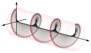
Polarization: A Key to Effective Communication Polarization, whether circular, vertical, or horizontal, is a fundamental property of electromagnetic waves that can significantly impact the efficiency of signal transmission and reception. The chapter examines how different antenna designs, such as crossed dipoles and helical antennas, achieve various polarization modes. This knowledge is essential for applications ranging from satellite communication to terrestrial point-to-point links.
Helical and Parabolic Antennas: Advanced Designs for Specific Needs The chapter also explores the characteristics and applications of helical beam and parabolic antennas. Helical antennas, known for their versatility in polarization, are discussed in terms of their design parameters and reception capabilities. Parabolic antennas, with their high-gain characteristics, are dissected to understand how their size and shape influence their performance. These discussions are particularly relevant for amateur radio operators interested in long-distance communication and satellite operations.
Understanding Current and Voltage Distribution on Antennas
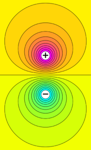
The Intricacies of Antenna Behavior In the realm of amateur radio, the mastery of antenna principles is essential for advanced operators. This chapter delves into the nuanced aspects of current and voltage distribution on antennas, particularly focusing on the half-wave dipole, a staple in ham radio setups. Understanding these distributions is not just about memorizing patterns; it involves comprehending the underlying electromagnetic principles that govern how antennas transmit and receive signals. This knowledge is critical for optimizing antenna design, improving communication efficiency, and troubleshooting issues in radio setups.
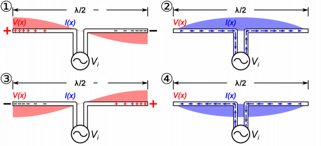
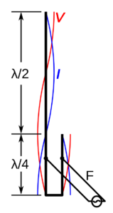
The Half-Wave Dipole: A Case Study The half-wave dipole serves as a prime example throughout this chapter, showcasing typical phenomena in antenna operation. Key topics include the variations in voltage and current along the antenna’s length, the significance of impedance, and the optimal points for feeding the antenna. These concepts are intricately linked, each influencing antenna performance in unique ways. For instance, knowing why the voltage is highest at the ends and the current peaks at the center can guide operators in effective antenna positioning and tuning.
Bridging Theory and Practice Each question in this chapter not only addresses a specific aspect of antenna theory but also ties it back to practical applications in ham radio. The discussions range from the fundamental principles of RF engineering to their implications in real-world scenarios. By the end of this chapter, learners will have a comprehensive understanding of how current and voltage distribution affects antenna performance, a knowledge base that is indispensable for anyone aiming to achieve advanced proficiency in amateur radio.
Antenna Feed Arrangements – Tee, Gamma, Stubs
This chapter explores the complex and essential world of antenna feed arrangements, focusing specifically on Tee, Gamma, and Stub matches. These arrangements are pivotal in amateur radio and RF engineering for ensuring that antennas are efficiently matched to their transmission lines, a key factor in effective radio communication. The chapter begins with the T match, a method used to connect high-impedance transmission lines to lower-impedance antennas by spacing connections at specific intervals on either side of the driven element. This technique is vital for maintaining effective communication between the antenna and the transmission line, especially when impedance discrepancies exist.
Next, the chapter delves into the gamma match, a common and versatile method used predominantly in Yagi antenna systems. This unbalanced feed system, which involves connections at the antenna’s center and a fraction of a wavelength to one side, plays a crucial role in balancing the antenna system, ensuring that it operates efficiently across various frequencies. Understanding the gamma match is essential for amateur radio enthusiasts and professionals who work with Yagi and similar antenna types.
The final key focus is on the stub match, a technique that involves using a short section of transmission line for impedance matching. This method is particularly useful in scenarios where other types of matching might be impractical or overly complex. The chapter also addresses practical applications of these concepts, such as calculating the physical length of coaxial stubs for specific frequencies, highlighting the real-world relevance of these theoretical principles. By comprehensively covering these fundamental antenna feed arrangements, the chapter equips readers with the knowledge to design and optimize a wide range of antenna systems.

Velocity Factor and Impedance Effects in Transmission Lines
This chapter delves into the intricate concepts of velocity factor and the effects of terminating transmission lines in non-characteristic impedances, both of which are pivotal in the realm of amateur radio. The exploration begins with an understanding of the velocity factor, a key parameter that defines the speed at which signals propagate through transmission lines compared to their speed in a vacuum. This factor, influenced primarily by the dielectric materials within the transmission line, plays a crucial role in determining the physical and electrical lengths of lines, especially in antenna design and phasing adjustments. The chapter methodically unravels how different types of transmission lines, such as coaxial cables with specific dielectric materials like polyethylene, exhibit varying velocity factors, and how these factors impact the overall performance of radio communication systems.
Further, the chapter addresses the intriguing phenomena that occur when transmission lines are terminated in non-characteristic impedances. Through a series of questions, it elucidates how different lengths of transmission lines, such as quarter-wavelength and half-wavelength, behave differently when presented with open or shorted conditions at their ends. These scenarios lead to various impedance transformations, a concept critical in the design and optimization of RF systems. Understanding these transformations allows for effective impedance matching, a necessity for minimizing signal reflection and loss in radio communications.
Integrating these concepts, the chapter establishes a foundational understanding essential for amateur radio operators and RF engineers. It highlights the practical applications of these theories in real-world scenarios, ranging from constructing resonant antennas to optimizing the transmission line lengths for specific frequency operations. This comprehensive exploration equips enthusiasts and professionals alike with the knowledge to enhance the efficiency and efficacy of their radio systems, reflecting the interconnectivity and relevance of velocity factor and impedance transformations in amateur radio.
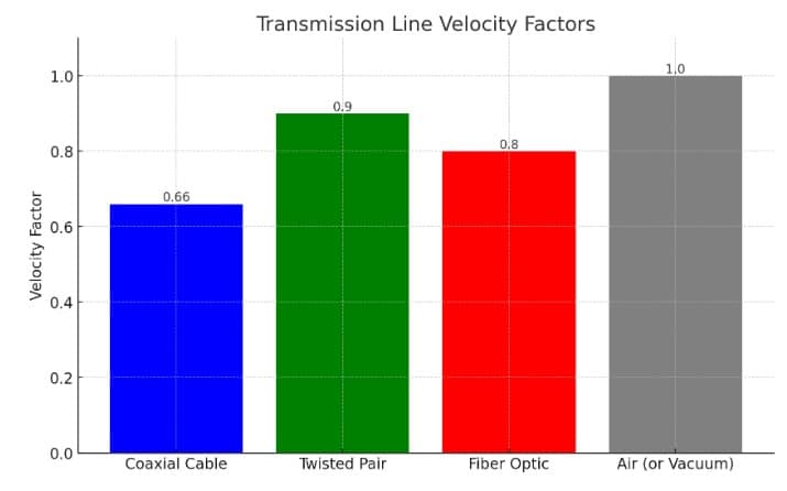
The graph above illustrates the concept of the Velocity Factor in various types of transmission lines, including Coaxial Cable, Twisted Pair, Fiber Optic, and Air (or Vacuum) as a reference. The Velocity Factor represents the speed at which an electromagnetic wave travels through the transmission line compared to the speed of light in a vacuum.
- Coaxial Cable: Shows a Velocity Factor of 0.66, indicating that signals travel at 66% of the speed of light in this medium.
- Twisted Pair: Has a Velocity Factor of 0.9, with signals traveling at 90% of the speed of light, making it faster than coaxial cable but still slower than in a vacuum.
- Fiber Optic: Demonstrates a Velocity Factor of 0.8, where signals travel at 80% of the speed of light. This is typically due to the refractive index of the glass or plastic used in the fiber.
- Air (or Vacuum): Represents the baseline with a Velocity Factor of 1.0, as electromagnetic waves travel at the speed of light in a vacuum.
The graph underscores the impact of the transmission medium on the propagation speed of electromagnetic waves, which is a critical factor in designing communication systems to ensure efficient signal transmission over distances.
Antenna Tuner/Transmatch, Impedance Matching Circuits
In the realm of amateur radio, the efficient transfer of power from transmitters to antennas is pivotal, and this chapter meticulously explores antenna tuners and impedance matching circuits, which are central to this process. The chapter begins with an in-depth examination of various antenna tuners, including transformer-type, series-type, L-type, and Pi-type, each characterized by unique configurations and specialized applications. Understanding the operational principles and distinctions among these tuners is crucial for effective impedance matching in diverse radio communication scenarios.
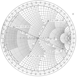
The narrative then shifts to the core concepts of impedance matching networks, particularly focusing on the pi-network and its advanced variant, the pi-L network. These networks, integral to adjusting impedance levels for optimal power transmission, are analyzed for their efficiency and suitability in different amateur radio setups. Additionally, the chapter introduces the Smith Chart, a graphical tool indispensable for addressing impedance matching and transmission line challenges in RF engineering. This comprehensive exploration aims to equip amateur radio operators, especially those progressing towards an Advanced Licence qualification in Canada, with the knowledge and skills necessary to optimize their radio systems for enhanced performance.
Performance Limitations in Receivers
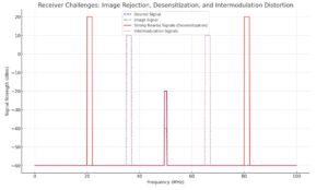
Welcome to the exploration of “Performance Limitations in Receivers.” This chapter is dedicated to understanding the various challenges and constraints that affect the performance of radio receivers, particularly in complex signal environments. Students and enthusiasts will engage with critical concepts such as image rejection, receiver desensitization, and intermodulation distortion. Each question and answer segment is designed to incrementally build a comprehensive understanding of how different factors like the RF amplifier pre-selector and strong nearby signals can impact receiver functionality. By delving into these technical aspects, this chapter aims to equip learners with a deeper insight into receiver design and operation, enhancing their ability to diagnose and resolve common issues in radio communication systems.

Receiver Components and Functions
Welcome to the chapter on “Detection, Audio, Automatic Gain Controls.” This section is designed to deepen the understanding of crucial components and mechanisms within modern communication receivers, particularly relevant in amateur radio. Over the course of this chapter, participants will explore intricate aspects of receiver technology, covering topics such as the role of de-emphasis networks in FM receivers, the functionality of product detectors, and the dynamics of Automatic Gain Control (AGC) systems. Key questions will guide learners through the nuances of signal processing, from detection to audio output, and the critical role of AGC in maintaining consistent signal quality. This journey through receiver technology will provide insights into how receivers manage varying signal strengths, demodulate complex signal types, and ensure clear audio reproduction. The knowledge gained here is essential for anyone interested in the technical aspects of radio communication, offering valuable skills for both amateur radio enthusiasts and professionals in the field.
Enhancing Receiver Performance
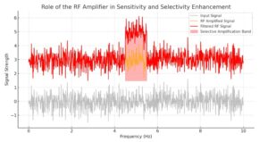
In this chapter, participants will explore the functionalities and significance of RF and IF amplifiers and understand the concept of selectivity in superheterodyne receivers. The course will provide detailed explanations for 11 key questions, starting with understanding the ‘noise floor’ of a receiver (Question A-006-003-001) and its impact on signal detection. The role of the first IF amplifier stage in improving selectivity and gain (Question A-006-003-002), and the appropriate gain levels for RF amplifiers (Question A-006-003-003) will be examined, giving insights into how these components influence receiver sensitivity and performance.
Learners will also delve into the primary purpose of RF amplifiers in improving noise figure (Question A-006-003-004) and how receiver sensitivity is often expressed for UHF FM receivers (Question A-006-003-005). The concept of ‘dynamic range’ in receivers (Question A-006-003-006), the effect of lower noise figures on receiver sensitivity (Question A-006-003-007), and the origin of noise in well-designed receivers (Question A-006-003-008) will be covered, providing a comprehensive understanding of receiver noise management.
Further, the course will discuss why very low noise figures are less critical for high-frequency receivers (Question A-006-003-009) and define the term ‘dynamic range’ in the context of signal amplitude levels during reception (Question A-006-003-010). Lastly, the role of the preselector in front-end selectivity (Question A-006-003-011) will be explored, highlighting its importance in filtering and signal reception.
Through this chapter, participants will gain a thorough understanding of the key components in superheterodyne receivers and how they contribute to optimizing receiver performance, especially in the realm of amateur radio
Course Introduction: Dissecting Superheterodyne Receiver Components
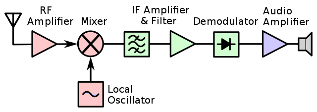
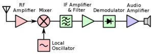
This chapter provides an overview of the critical components in superheterodyne receivers by explaining the answers to 11 key questions. The course starts by exploring the mixer stage’s role in frequency conversion (Question A-006-002-001), demonstrating how it changes the incoming signal to the Intermediate Frequency (IF). Learners will understand the necessity of the Beat-Frequency Oscillator (BFO) in Single Sideband (SSB) reception (Question A-006-002-002) and delve into the functionality of the first mixer in producing the IF (Question A-006-002-003). The course also addresses practical scenarios, such as calculating the local oscillator frequency for precise signal reception (Question A-006-002-004).
Further, the course examines the offset function of the BFO relative to the incoming signal for effective SSB signal detection (Question A-006-002-005) and emphasizes the importance of oscillator stability and spectral purity in superheterodyne receivers (Question A-006-002-006). Tuning mechanisms, critical for aligning the local oscillator and ensuring accurate frequency reception, are discussed (Questions A-006-002-007 and A-006-002-008). Additionally, the process of combining signals in the mixer stage to produce the IF is explored (Question A-006-002-009), alongside an examination of which receiver stages have input circuits tuned to the same frequency for optimal mixing and selectivity (Question A-006-002-010). The chapter concludes by reiterating the primary function of the mixer stage in generating the IF (Question A-006-002-011), consolidating learners’ understanding of these fundamental concepts in radio technology.
Single, Double-Conversion Superheterodyne Architectures
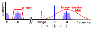
This chapter provides a comprehensive analysis of both single and double-conversion superheterodyne architectures. It covers the essential aspects of frequency conversion, the role of intermediate frequencies, and the specific advantages of using superheterodyne techniques, such as improved selectivity and optimized circuit design. The exploration into double-conversion receivers highlights their superiority in reducing image interference and enhancing overall receiver performance. For amateur radio enthusiasts and professionals alike, this chapter demystifies the complex engineering behind these receivers, explaining how they achieve superior signal processing and clarity.
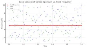
The Dynamics of Elusive Communications: Unpacking Spread Spectrum
“The Dynamics of Elusive Communications” offers a detailed exploration into the world of spread spectrum technologies, a pivotal aspect of modern wireless communication, including amateur radio. This chapter demystifies the concepts of frequency hopping and direct sequence spread spectrum. By unraveling the workings of these techniques, it provides insight into how spread spectrum communication effectively distributes a signal over a wide frequency band, enhancing resistance to interference and eavesdropping. For amateur radio enthusiasts, understanding these technologies is crucial, especially in environments with dense signal traffic or where secure, reliable communication is paramount. This chapter serves as a guide to the intricate mechanisms of spread spectrum, shedding light on its applications and advantages in the field of ham radio.
Codes and Protocols: Baudot, ASCII, Parity, CRC, X.25, ISO Layers
Unveiling Digital Mysteries: A Deep Dive into Codes and Protocols
In “Unveiling Digital Mysteries: A Deep Dive into Codes and Protocols,” the chapter embarks on an exploratory journey through the foundational digital codes and communication protocols integral to ham radio. It demystifies complex concepts such as Baudot, ASCII, parity checks, Cyclic Redundancy Check (CRC), and the intricacies of the X.25 standard and OSI model layers. This comprehensive examination is essential for anyone delving into digital modes of amateur radio, providing a clear understanding of the mechanisms behind data encoding, error detection, and structured communication protocols. By dissecting these technical elements, the chapter equips readers with the knowledge necessary to navigate the digital landscape of ham radio, enhancing their ability to engage in advanced digital communications effectively.
