
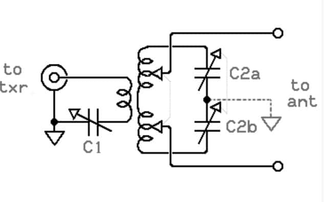
A-007-001-001: For an antenna tuner of the “Transformer” type, which of the following statements is FALSE?
Antenna Tuner Misconceptions (A-007-001-001)
Unraveling Transformer-Type Tuner Myths
In addressing Question A-007-001-001, it’s crucial to understand the differences between transformer-type and Pi-type antenna tuners. The false statement, B. The circuit is known as a Pi-type antenna tuner, highlights a common misconception. Transformer-type tuners are specifically designed to match a broad range of antenna impedances to the standard 50-ohm output of most transmitters. They do this by utilizing a configuration of transformers, which is different from the operational principle of Pi-type tuners.
Pi-type antenna tuners, conversely, use a different configuration, typically involving an inductor and two capacitors, forming the shape of the Greek letter Pi (π). This design is particularly effective in matching a wide range of impedances, including very high or very low values, to a transmitter’s 50-ohm output. Understanding these distinctions is vital for amateur radio operators, as the correct choice of an antenna tuner significantly affects the performance and efficiency of their radio setup. Recognizing the specific applications and limitations of each tuner type enables operators to make informed decisions when configuring their stations.
Parallels:
- Kitchen Appliance Analogy: Comparing a blender to a food processor illustrates how each has a specific role, much like transformer-type and Pi-type tuners. The blender, suited for mixing and liquefying, represents the transformer-type tuner’s ability to match a range of impedances. In contrast, the food processor’s versatility, akin to the Pi-type tuner, allows it to handle a broader range of tasks effectively.
- Transportation Comparison: A city bus versus a sports car analogy demonstrates the specialized functions of different antenna tuners. The bus, like a transformer-type tuner, is designed for a specific function — carrying passengers over various routes, paralleling the tuner’s impedance matching range. The sports car, similar to the Pi-type tuner, offers flexibility and performance, capable of adapting to a wide range of driving conditions, much like the tuner’s impedance matching capabilities.
Key Takeaways:
- Distinct Tuner Types: Transformer-type and Pi-type antenna tuners have different configurations and applications, making them suitable for specific impedance matching scenarios.
- Misidentification: It is a misconception to refer to a transformer-type tuner as a Pi-type tuner. Each type has its unique designation and functionality.
- Transformer-Type Tuner Function: These tuners are specifically designed to match a wide range of antenna impedances to the standard 50-ohm output of most transmitters, enhancing compatibility and performance.
- Pi-Type Tuner Configuration: Pi-type tuners utilize a configuration of one inductor and two capacitors, making them effective in matching a diverse range of impedance values.
- Operational Understanding: A clear understanding of the differences between these tuner types is essential for efficient and effective operation in ham radio setups.
A-007-001-002: For an antenna tuner of the “Series” type, which of the following statements is FALSE?
Series-Type Antenna Tuners: Fact vs. Fiction (A-007-001-002)
Dispelling Series-Type Tuner Confusions
Question A-007-001-002 challenges a common misunderstanding about series-type antenna tuners. The false statement, D. The circuit is known as a Pi-type antenna tuner, distinguishes series-type tuners from Pi-type tuners. Series-type antenna tuners, known for their simplicity, are specifically designed for matching a range of impedances to a transmitter’s standard 50-ohm output. They achieve this through a series configuration of components, which is fundamentally different from the parallel configuration used in Pi-type tuners. Understanding these differences is key for amateur radio operators to effectively utilize the right type of tuner for their specific needs.
The series-type tuner, due to its design, is particularly suited for situations where the antenna impedance is not excessively high or low. This makes them a popular choice for amateur radio operators who need a straightforward, efficient solution for impedance matching with moderate impedance ranges. Knowing when to use a series-type tuner, as opposed to a Pi-type tuner, can significantly impact the performance and efficiency of a ham radio setup.
Parallels:
- Musical Instruments Analogy: Think of series-type and Pi-type tuners like two different musical instruments – a guitar and a piano. A guitar (series-type tuner) is straightforward, offering a direct approach to producing music, suitable for a range of styles but with limitations in complexity. Similarly, the piano (Pi-type tuner) offers a broader range of notes and chords, suitable for more complex musical compositions, analogous to the Pi-type tuner’s ability to handle a wider range of impedance values.
- Sports Equipment Comparison: Comparing a series-type tuner to a set of dumbbells and a Pi-type tuner to a multi-gym setup can illustrate their differences. Dumbbells (series-type tuner) are simple and effective for a range of exercises but have limitations. In contrast, a multi-gym (Pi-type tuner) offers more versatility and options, similar to how Pi-type tuners can handle a broader range of impedance scenarios.
Key Takeaways:
- Series vs. Pi-Type: Series-type tuners are distinct from Pi-type tuners, especially in their component configuration and impedance matching capabilities.
- Misconception Clarified: A series-type antenna tuner should not be confused with a Pi-type tuner, each having unique characteristics and applications.
- Series-Type Tuner Use: These tuners are efficient for moderate impedance ranges, making them suitable for many standard ham radio setups.
- Application Suitability: Understanding when to use a series-type tuner versus a Pi-type tuner is crucial for optimizing antenna performance in amateur radio.
- Component Configuration: The series arrangement of components in series-type tuners offers a more straightforward approach to impedance matching compared to the more complex Pi-type configuration.
A-007-001-004: For an antenna tuner of the “Pi” type, which of the following statements is FALSE?
Pi-Type Antenna Tuner Clarification (A-007-001-004)
Demystifying Pi-Type Tuner Configuration
Question A-007-001-004 seeks to clarify a common misunderstanding about Pi-type antenna tuners. The false statement, B. The circuit is a series-type antenna tuner, differentiates Pi-type tuners from series-type tuners. Pi-type tuners are named for their resemblance to the Greek letter Pi (π) in the circuit diagram, consisting of an inductor flanked by two capacitors. This configuration is particularly effective for a wide range of impedance matching, from very low to very high values, which is significantly different from the series configuration used in series-type tuners.
The versatility of the Pi-type tuner lies in its ability to both match impedance and filter out unwanted frequencies, making it a popular choice in complex ham radio setups. Its design allows for efficient power transfer across a wide variety of antenna types and impedance values, a critical aspect for effective radio communication. Understanding the specific design and application of Pi-type tuners is vital for amateur radio operators to optimize their station’s performance.
Parallels:
- Gardening Tools Analogy: Imagine comparing a Pi-type tuner to a Swiss Army knife and a series-type tuner to a standard knife. The Swiss Army knife (Pi-type tuner) is versatile, equipped to handle a range of tasks, similar to the Pi-type tuner’s ability to match various impedances and filter frequencies. The standard knife (series-type tuner), while effective for specific tasks, lacks the multifunctionality of the Swiss Army knife.
- Art Supplies Comparison: Think of Pi-type and series-type tuners like different art supplies. The Pi-type tuner is like a set of mixed media art supplies, capable of creating a variety of artistic effects, paralleling its versatility in impedance matching and frequency filtering. In contrast, the series-type tuner is like a graphite pencil, excellent for specific types of drawing but limited in its range of applications.
Key Takeaways:
- Circuit Design: Pi-type tuners are characterized by their Pi-like circuit configuration, differing significantly from series-type tuners.
- Versatility in Impedance Matching: These tuners can efficiently match a wide range of impedance values, from very low to very high.
- Frequency Filtering: Beyond impedance matching, Pi-type tuners also offer the capability to filter out unwanted frequencies.
- Optimal for Complex Setups: Their versatility makes Pi-type tuners suitable for more complex ham radio setups.
- Understanding Applications: Knowing when to use a Pi-type tuner is key to optimizing the performance of a ham radio station.
A-007-001-006: Which type of network offers the greatest transformation ratio?
The Superiority of Pi-Networks in Transformation (A-007-001-006)
Assessing Pi-Networks’ Transformation Capabilities
Question A-007-001-006 delves into the transformation capabilities of different network types, with the correct answer, A. Pi-network, indicating the pi-network’s superior ability in this regard. Pi-networks are particularly adept at providing a high transformation ratio, making them ideal for situations where a significant impedance mismatch needs to be addressed. This capability is due to their unique configuration, which allows for a wide range of adjustment in impedance values.
The pi-network’s versatility in impedance transformation is crucial in amateur radio, especially in complex setups where antennas and transmitters may have widely differing impedance values. The ability of a pi-network to efficiently bridge these differences ensures optimal power transfer and minimizes signal loss, which is key to effective communication and operation in ham radio.
Parallels:
- Gearbox Analogy: Think of a pi-network as a gearbox in a vehicle. Just as a gearbox can adjust the torque and speed ratio to suit different driving conditions, a pi-network can adjust impedance levels to ensure efficient power transfer under various radio operating conditions.
- Audio Equalizer Comparison: A pi-network can be likened to an audio equalizer used in sound systems. Just as an equalizer adjusts different frequency bands to achieve the desired sound quality, a pi-network adjusts impedance levels to optimize the performance of radio circuits.
Key Takeaways:
- High Transformation Ratio: Pi-networks excel in providing a high transformation ratio, making them suitable for handling significant impedance mismatches.
- Versatile Impedance Adjustment: The ability to adjust a wide range of impedance levels makes pi-networks invaluable in various ham radio setups.
- Optimal Power Transfer: Efficient impedance matching by pi-networks ensures optimal power transfer and minimal signal loss in radio communication.
- Crucial for Complex Setups: Their superiority in impedance transformation makes pi-networks particularly useful in complex ham radio configurations.
- Comparative Advantage: Compared to other network types, pi-networks offer greater flexibility and effectiveness in impedance matching.
A-007-001-007: Why is an L-network of limited utility in impedance matching?
Limitations of L-Networks in Impedance Matching (A-007-001-007)
Exploring L-Networks’ Impedance Matching Range
Question A-007-001-007 addresses the limited utility of L-networks in impedance matching. The correct answer, A. It matches only a small impedance range, points out the primary limitation of L-networks. While L-networks are simple and effective in certain scenarios, their ability to match impedance is confined to a relatively narrow range. This is due to their basic configuration, typically consisting of a single inductor and a single capacitor, which does not allow for as wide a range of impedance transformation as more complex networks.
The limitation in impedance matching range means that L-networks are not suitable for all antenna types or conditions, especially those with significant impedance mismatches. Amateur radio operators need to understand these limitations to choose the appropriate type of network for their specific needs, ensuring efficient operation and optimal performance of their radio equipment.

Parallels:
- Basic Tool Analogy: An L-network can be compared to a standard screwdriver in a toolbox. Just like the screwdriver is effective for certain types of screws but not all, an L-network is suitable for specific impedance ranges but cannot accommodate the wider variety seen in more complex radio setups.
- Cooking Utensil Comparison: Think of an L-network like a regular frying pan in a kitchen. While the frying pan is great for a range of cooking tasks, it has its limitations and isn’t suitable for tasks requiring a pressure cooker or a grill, just as L-networks have their limitations in impedance matching.
Key Takeaways:
- Narrow Impedance Range: L-networks are limited by their ability to match only a small range of impedances, restricting their utility in diverse radio setups.
- Simple Configuration: The basic configuration of L-networks, while advantageous for simplicity and low insertion loss, contributes to their limited impedance matching capability.
- Suitability for Specific Scenarios: Understanding where L-networks are effective and where they fall short is crucial for proper network selection in ham radio applications.
- Impedance Matching Limitations: Recognizing the limitations of L-networks helps amateur radio operators avoid suboptimal performance in their setups.
- Choosing the Right Network: The selection of an impedance matching network should be based on the specific requirements of the antenna system and the operating conditions.
A-007-001-009: What advantage does a pi-L network have over a pi-network for impedance matching between a vacuum tube linear amplifier and a multiband antenna?
Pi-L Network vs. Pi-Network in Linear Amplifiers (A-007-001-009)
Comparing Harmonic Suppression Capabilities
Question A-007-001-009 delves into the advantages of using a pi-L network over a pi-network for impedance matching between a vacuum tube linear amplifier and a multiband antenna. The correct answer, D. Greater harmonic suppression, highlights the pi-L network’s enhanced capability in suppressing unwanted harmonic frequencies. This feature is particularly crucial when operating a linear amplifier with a multiband antenna, as it helps in reducing interference and maintaining a clean signal output.
The pi-L network adds an additional inductor to the traditional pi-network configuration, which significantly improves its ability to suppress harmonics. This makes the pi-L network a preferred choice in setups where maintaining signal purity is critical, such as in amateur radio stations that operate across multiple bands and need to minimize interference.
Parallels:
- Noise-Canceling Headphones Analogy: The pi-L network’s harmonic suppression can be likened to the function of noise-canceling headphones. Just as these headphones filter out unwanted ambient noise for a clearer audio experience, the pi-L network filters out harmonics for cleaner radio signals.
- Water Filtration System Comparison: Think of the pi-L network like a water filtration system with an extra filter stage. This additional stage (extra inductor) provides enhanced purification, similar to how the pi-L network more effectively suppresses harmonics compared to a standard pi-network.
Key Takeaways:
- Enhanced Harmonic Suppression: The pi-L network offers greater harmonic suppression compared to a standard pi-network, making it ideal for linear amplifier applications.
- Additional Inductor Advantage: The inclusion of an extra inductor in the pi-L network is key to its improved harmonic filtering capabilities.
- Importance in Multiband Operation: This enhanced suppression is particularly beneficial in multiband antenna setups, where maintaining signal integrity across bands is essential.
- Choice for Signal Purity: Amateur radio operators should consider the pi-L network for applications where minimizing interference is critical.
- Comparative Benefit: Understanding the comparative advantages of different network types, like the pi-L and pi-network, is crucial for optimal system design.
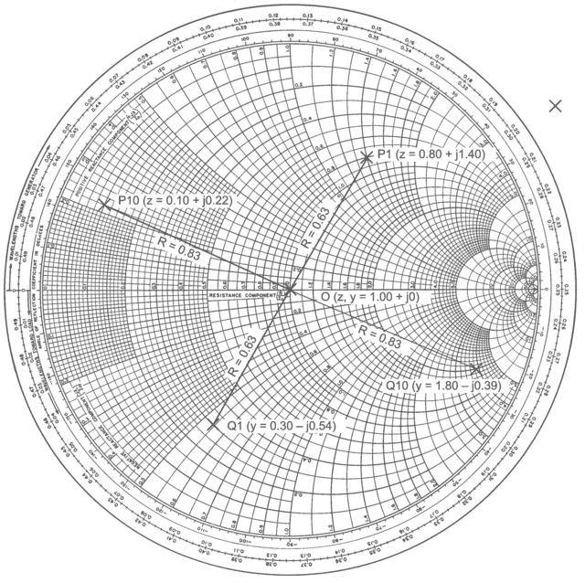
A-007-001-011: A Smith Chart is useful:
The Practicality of Smith Charts (A-007-001-011)
Understanding the Smith Chart’s Role in RF Engineering
Question A-007-001-011 explores the utility of a Smith Chart in amateur radio applications. The correct answer, B. because it simplifies mathematical operations, highlights the Smith Chart’s specific role in RF engineering. A Smith Chart is a graphical tool used to solve problems related to impedance matching and transmission lines. It simplifies the complex calculations involved in dealing with RF circuits, making it an invaluable resource for amateur radio operators and engineers.
The Smith Chart allows for a visual representation of complex impedances and their transformations, facilitating easier analysis and design of transmission lines and matching networks. Its ability to provide a quick and intuitive understanding of these concepts is particularly beneficial in the complex world of RF engineering, where precision and efficiency are key.
Parallels:
- Map Navigation Analogy: Think of a Smith Chart like a map for a city. Just as a map helps you navigate through streets and find the best routes, a Smith Chart helps in navigating through impedance values and finding the best paths for impedance matching.
- Cookbook Comparison: A Smith Chart can be likened to a cookbook for chefs. Just as a cookbook provides recipes and guidelines for preparing various dishes, a Smith Chart provides guidelines and visual cues for solving impedance matching and transmission line problems.
Key Takeaways:
- Specific Use in RF Engineering: The Smith Chart is primarily used for solving problems related to impedance matching and transmission lines in RF circuits.
- Graphical Tool: It offers a visual method to represent and analyze complex impedances and their transformations.
- Simplifying Complex Calculations: The Smith Chart simplifies the intricate calculations involved in RF engineering, making it a practical tool for amateurs and professionals.
- Essential for Impedance Analysis: Its ability to visually represent impedance relationships is invaluable for designing and troubleshooting RF systems.
- Precision and Efficiency: The Smith Chart aids in achieving precision and efficiency in RF circuit design and analysis