
Start Here
Performance Limitations in Receivers
Welcome to the exploration of “Performance Limitations in Receivers.” This chapter is dedicated to understanding the various challenges and constraints that affect the performance of radio receivers, particularly in complex signal environments. Students and enthusiasts will engage with critical concepts such as image rejection, receiver desensitization, and intermodulation distortion. Each question and answer segment is designed to incrementally build a comprehensive understanding of how different factors like the RF amplifier pre-selector and strong nearby signals can impact receiver functionality. By delving into these technical aspects, this chapter aims to equip learners with a deeper insight into receiver design and operation, enhancing their ability to diagnose and resolve common issues in radio communication systems.

A-006-005-001: What part of a superheterodyne receiver determines the image rejection ratio of the receiver?
Image Rejection in Superheterodyne Receivers (A-006-005-001)
Determining Image Rejection Ratio in Receivers
Question (A-006-005-001) asks about the component in a superheterodyne receiver that determines the image rejection ratio. The correct answer, A. RF amplifier pre-selector, points to the significance of this component in minimizing image frequency interference. In superheterodyne receivers, image frequencies are unwanted signals that can be received due to the mixing process in the RF stage. These frequencies are mirror images of the desired signal and can cause interference, reducing the receiver’s effectiveness.
The RF amplifier pre-selector, often comprising filters and tuned circuits, plays a crucial role in attenuating these image signals. It acts before the signal reaches the mixer, filtering out frequencies that are not within the desired range. By doing so, it significantly enhances the receiver’s ability to isolate and process the intended signal while rejecting the image frequencies. This selectivity is key in crowded signal environments and is essential for achieving clear and accurate signal reception in amateur and professional radio applications.

Parallels:
- Selective Hearing in a Noisy Room: Like focusing on a single voice amidst multiple conversations, the pre-selector filters out unwanted image frequencies.
- Quality Control in Manufacturing: Similar to inspecting products for defects before packaging, the pre-selector filters signals before further processing.
Question Summary and Key Takeaways:
- RF Pre-selector’s Role: Critical in determining the receiver’s image rejection capability.
- Filters Out Image Frequencies: Enhances the receiver’s ability to reject unwanted mirror images of signals.
- Improves Signal Clarity: Essential for clear reception by minimizing interference.
- Key in Crowded Signal Environments: Especially valuable where multiple signals are present.
- Integral to Receiver Design: A fundamental component for high-quality superheterodyne receivers.
A-006-005-002: What is the term for the reduction in receiver sensitivity caused by a strong signal near the received frequency?
Desensitization in Receivers (A-006-005-002)
Understanding Receiver Desensitization
Question (A-006-005-002) focuses on the phenomenon that causes a reduction in receiver sensitivity due to a strong signal near the received frequency. The correct answer, B. Desensitization, describes how strong nearby signals can overload the receiver’s front end, making it less effective at picking up weaker signals. This situation is akin to a radio becoming less sensitive to the signals it’s supposed to receive because it’s overwhelmed by stronger ones close by. Desensitization occurs when the receiver’s amplifiers or mixer are driven into non-linear operation by the strong signal, effectively raising the noise floor and thereby masking weaker signals that the receiver would normally detect.

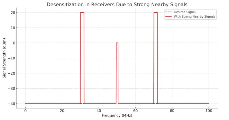
The graph illustrates the concept of desensitization in receivers, a condition where strong nearby signals can overload the receiver’s front end, making it less effective at picking up weaker desired signals.
- Desired Signal (Blue Dashed Line): Represents a weak signal that the receiver aims to pick up, shown here at around 50 MHz with a strength of -40 dBm. This is the signal of interest that the receiver is tuned to receive.
- With Strong Nearby Signals (Red Line): Demonstrates how the presence of strong nearby signals at around 30 MHz and 70 MHz, each with a strength of 20 dBm, can impact the receiver. These strong signals can overload the receiver’s front end, leading to desensitization.
Desensitization reduces the receiver’s sensitivity to the desired signal due to the front-end overload caused by the strong nearby signals. This phenomenon makes it challenging for the receiver to discern the weaker desired signal amidst the stronger, undesired signals, thereby impacting the receiver’s effectiveness and overall performance in crowded signal environments.
Parallels:
- Overwhelmed Listener in a Loud Environment: Just as it’s hard to hear a quiet voice in a noisy room, a receiver finds it difficult to detect weak signals in the presence of strong ones.
- Bright Lights Washing Out Fainter Ones: Like city lights making it hard to see stars, strong nearby signals can obscure weaker ones in a receiver.
Question Summary and Key Takeaways:
- Desensitization Impact: Reduces the receiver’s ability to detect weak signals due to strong nearby ones.
- Front-End Overload: Strong signals can push the receiver into non-linear operation.
- Raising Noise Floor: The presence of strong signals increases the overall noise level, masking weaker ones.
- Challenges in Receiver Design: A significant factor to consider in designing sensitive receivers.
- Importance in Radio Communication: Understanding desensitization helps in optimizing receiver performance, especially in crowded frequency environments.
A-006-005-003: What causes receiver desensitization?
Causes of Receiver Desensitization (A-006-005-003)
Factors Leading to Desensitization
Question (A-006-005-003) asks about the cause of receiver desensitization. The correct answer, D. Strong near-frequency signals, highlights the primary factor leading to this issue. Desensitization is caused when strong signals close to the frequency the receiver is tuned to overload its circuitry. This overload can happen in the RF amplifier or mixer stages, where the strong signals force these components to operate outside their optimal linear range. The result is a diminished ability of the receiver to process and detect the weaker signals it is supposed to receive.
Parallels:
- Loud Noises Drowning Out Conversation: Similar to trying to focus on a conversation while loud noises nearby drown it out.
- Bright Spotlight Near a Dimmer Light: Like a bright spotlight making it hard to see a dimmer light next to it, strong signals can overpower weaker ones in a receiver.
Question Summary and Key Takeaways:
- Strong Signals Cause Desensitization: Nearby strong signals are the primary reason for receiver desensitization.
- Overload in RF Amplifier/Mixer: These components are particularly susceptible to overload by strong signals.
- Reduces Signal Processing Ability: Limits the receiver’s capacity to handle and detect weaker signals.
- Challenge in Crowded Frequency Bands: Especially problematic in environments with many strong signals.
- Critical for Effective Receiver Design: Understanding and mitigating desensitization is key for high-performance receivers.
A-006-005-004: What is one way receiver desensitization can be reduced?
Reducing Receiver Desensitization (A-006-005-004)
Mitigating Desensitization in Receiver Design
Question (A-006-005-004) explores a method to reduce receiver desensitization. The correct answer, B. Use a cavity filter, suggests a practical solution for mitigating the impact of strong nearby signals. Cavity filters are highly selective and can be tuned to reject unwanted frequencies effectively. By implementing these filters in the receiver design, particularly at the RF stage, they can prevent strong out-of-band signals from overloading the receiver’s front end, thereby maintaining the sensitivity needed to receive weaker signals. The use of cavity filters is particularly beneficial in environments where receivers are exposed to a range of signal strengths, ensuring that the receiver remains sensitive to the intended frequency.
Parallels:
- Noise-Canceling Headphones: Like noise-canceling headphones that block unwanted ambient sound, cavity filters block out unwanted radio signals.
- Selective Hearing in a Crowd: Similar to focusing on a single voice in a noisy environment, cavity filters help the receiver focus on specific frequencies.
Question Summary and Key Takeaways:
- Cavity Filters Reduce Desensitization: They are effective in filtering out strong nearby signals.
- Maintains Receiver Sensitivity: Ensures the receiver can still detect weaker signals.
- Used at RF Stage: Typically implemented at the RF input to maximize effectiveness.
- Crucial in Crowded Signal Environments: Particularly useful where the receiver is exposed to various signal strengths.
- Key Aspect of Receiver Design: Incorporating cavity filters can significantly enhance receiver performance.
A-006-005-005: What causes intermodulation in an electronic circuit?
Intermodulation in Electronic Circuits (A-006-005-005)
Understanding Intermodulation in Receivers
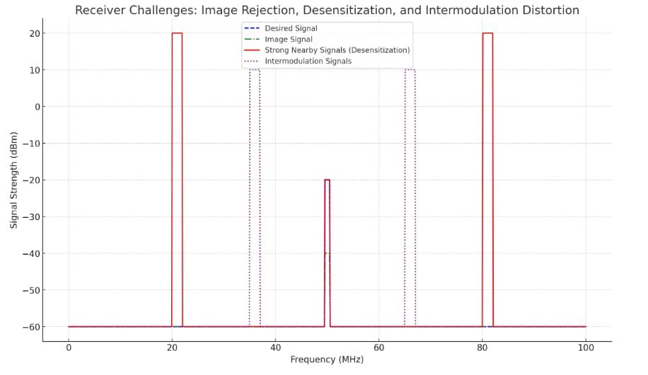
Question (A-006-005-005) asks about the cause of intermodulation in an electronic circuit. The correct answer, C. Nonlinear circuits or devices, points to the fundamental cause of intermodulation. This phenomenon occurs when signals mix in a nonlinear device, such as a mixer or amplifier, producing additional frequencies that are combinations or differences of the original frequencies. These unwanted frequencies, or intermodulation products, can create interference and distort the desired signal, degrading the receiver’s performance. Understanding and minimizing intermodulation is essential in receiver design, especially in environments with multiple strong signals, to ensure clear and accurate signal reception.
Parallels:
- Blending Colors in Art: Like mixing different paint colors to create new shades, signals mix in nonlinear circuits to produce new frequencies.
- Harmonics in Music: Similar to how instruments can create harmonics, mixing signals in a nonlinear circuit generates additional frequencies.
Question Summary and Key Takeaways:
- Nonlinear Circuits Cause Intermodulation: Mixing of signals in these circuits leads to additional frequencies.
- Creates Unwanted Frequencies: Intermodulation products can interfere with the desired signal.
- Impacts Signal Clarity: Leads to distortion and reduced performance in receivers.
- Prevalent in Strong Signal Environments: Particularly problematic where multiple strong signals are present.
- Crucial in Receiver Design: Mitigating intermodulation is key for maintaining signal integrity.
A-006-005-006: Which of the following is an important reason for using a VHF intermediate frequency in an HF receiver?
VHF Intermediate Frequency in HF Receivers (A-006-005-006)
Role of VHF IF in HF Receivers
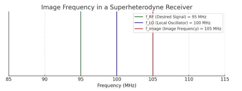
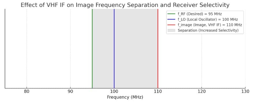
Question (A-006-005-006) addresses the importance of using a Very High Frequency (VHF) intermediate frequency in High Frequency (HF) receivers. The correct answer, C. To move the image response far away from the filter passband, explains that a higher IF helps in significantly reducing image frequency interference. Image frequencies are unwanted signals that a receiver can pick up due to the nature of frequency mixing. By using a VHF IF, the separation between the desired signal and its image frequency is increased, which effectively moves the image response well outside the passband of the receiver’s filters. This design choice enhances the receiver’s selectivity, allowing it to more effectively reject unwanted signals and focus on the intended frequency.
Parallels:
- Using Filters in Photography: Like using a filter to block out unwanted light in photography, a VHF IF helps block unwanted signals in HF receivers.
- Sorting Items on a Conveyor Belt: Similar to spacing items further apart on a conveyor belt for easier sorting, a VHF IF increases the separation between desired signals and image frequencies.
Question Summary and Key Takeaways:
- VHF IF Enhances Selectivity: Helps in effectively separating the desired signal from its image.
- Reduces Image Frequency Interference: Moves image response away from the filter passband.
- Increases Signal Separation: Provides a greater distance between target and image frequencies.
- Improves Receiver Performance: A higher IF frequency aids in better signal discrimination.
- Key Design Aspect for HF Receivers: Choosing the right IF frequency is crucial for optimal receiver function.
A-006-005-007: Intermodulation distortion is produced by:
Intermodulation Distortion in Receivers (A-006-005-007)
Causes and Effects of Intermodulation Distortion
Question (A-006-005-007) explores the source of intermodulation distortion in receivers. The correct answer, D. The mixing of two or more signals in the mixer of a superheterodyne receiver, points to a common cause of this distortion. Intermodulation distortion occurs when multiple signals interact within a non-linear component like a mixer, producing additional frequencies that are not present in the original signals. These unwanted frequencies can lead to interference and degrade the clarity and quality of the received signal. In a superheterodyne receiver, the mixer is a critical stage where such interactions can occur, especially in the presence of strong signals.
Parallels:
- Mixing Paints to Create New Colors: Like combining different paint colors to create unexpected new shades, mixing signals in a receiver can generate new frequencies.
- Blending Musical Notes: Similar to how blending different musical notes can produce harmonics, signals mixing in a receiver create intermodulation products.
Question Summary and Key Takeaways:
- Origin of Intermodulation Distortion: Generated by the mixing of signals in the receiver’s mixer.
- Production of Unwanted Frequencies: Creates frequencies not originally present in the signals.
- Can Degrade Signal Quality: Interference from these frequencies affects reception clarity.
- Common in Superheterodyne Receivers: Particularly prevalent where multiple strong signals are present.
- Important Consideration in Receiver Design: Understanding and mitigating this distortion is crucial for clear signal reception.
A-006-005-008: Which of the following is NOT a direct cause of instability in a receiver?
Stability Factors in Receivers (A-006-005-008)
Understanding Receiver Instability
Question (A-006-005-008) delves into the factors that do not directly cause instability in a receiver. The correct answer, B. Dial display accuracy, highlights that while important for user interface, dial accuracy is not a direct factor in the operational stability of a receiver. Instability in receivers is typically caused by factors such as mechanical rigidity, feedback components, and temperature variations, which can affect the performance of critical components like the local oscillator. These factors can lead to fluctuations in the receiver’s frequency or gain, impacting its ability to consistently receive and process signals.
Parallels:
- Stability in Building Structures: Just as a building’s stability is affected by its foundation and materials, not its address plaque, a receiver’s stability depends on its internal components, not its dial display.
- Vehicle Performance Not Defined by Speedometer Accuracy: A car’s performance is determined by its engine and design, much like a receiver’s stability is defined by its internal circuitry, not the display.
Question Summary and Key Takeaways:
- Dial Accuracy Not Linked to Stability: The accuracy of the dial display does not directly impact receiver stability.
- Mechanical and Electronic Factors Key: Components like local oscillators and feedback circuits play a significant role.
- Temperature Influences Performance: Variations can lead to frequency and gain instabilities.
- Stability Essential for Reliable Reception: Consistent performance is crucial for effective signal processing.
- Design Focus on Core Components: Emphasis should be on the stability of internal electronics for optimal functionality.
A-006-005-009: Poor frequency stability in a receiver usually originates in the:
Frequency Stability in Receivers (A-006-005-009)
Sources of Frequency Instability
Question (A-006-005-009) inquires about the usual origins of poor frequency stability in a receiver. The correct answer, A. Local oscillator and power supply, underscores the critical role these components play in maintaining accurate and stable tuning. The local oscillator’s stability is paramount as it directly influences the receiver’s ability to stay on the correct frequency. Similarly, fluctuations in the power supply can lead to variations in the performance of the local oscillator and other critical circuitry, thereby affecting the overall stability of the receiver.
Parallels:
- Clock Precision in Timekeeping: Like a clock’s mechanism dictating its timekeeping accuracy, the local oscillator and power supply determine the receiver’s frequency stability.
- Steady Power Supply in Computers: Similar to how consistent power affects a computer’s performance, stable power supply and oscillator are crucial for receiver accuracy.
Question Summary and Key Takeaways:
- Local Oscillator and Power Supply Key: These components are central to maintaining frequency stability.
- Influence on Tuning Accuracy: Fluctuations can lead to off-frequency reception.
- Consistency Vital for Performance: Stability in these areas is crucial for reliable receiver operation.
- Direct Impact on Signal Reception: Affects the ability to accurately process incoming signals.
- Design Focus for High-Quality Receivers: Emphasis on stable oscillator and power supply is essential.
A-006-005-010: Poor dynamic range of a receiver can cause many problems when a strong signal appears within or near the front-end bandpass. Which of the following is NOT caused as a direct result?
Dynamic Range and Receiver Performance (A-006-005-010)
Impact of Poor Dynamic Range on Receivers
Question (A-006-005-010) addresses the consequences of poor dynamic range in a receiver, especially when strong signals are present near the front-end bandpass. The correct answer, C. Feedback, indicates that feedback is not a direct result of poor dynamic range. However, poor dynamic range can lead to issues such as desensitization, where the receiver becomes less sensitive to weak signals, intermodulation, where unwanted signals are produced due to mixing of strong signals, and cross-modulation, where one strong signal modulates another signal. These problems can significantly degrade the quality of the received signal, making it difficult to extract useful information, especially in environments with a wide range of signal strengths.
Parallels:
- Overcrowded Party Conversation: Like struggling to focus on a conversation in a noisy room, a receiver with poor dynamic range has trouble isolating weak signals amidst strong ones.
- Photography in Extreme Lighting: Similar to a camera failing to capture details in scenes with high contrast, receivers with poor dynamic range struggle with signal extremes.
Question Summary and Key Takeaways:
- Consequences of Poor Dynamic Range: Leads to desensitization, intermodulation, and cross-modulation.
- Not Linked to Feedback: Feedback is not a direct result of poor dynamic range.
- Difficulty in Signal Extraction: Challenges in isolating desired signals from strong, nearby ones.
- Important in High-traffic Environments: Especially critical where signal strengths vary greatly.
- Focus on Receiver Design: Ensuring a good dynamic range is essential for high-quality signal reception.
A-006-005-011: Which of these measurements is a good indicator of VHF receiver performance in an environment of strong out-of-band signals?
VHF Receiver Performance in Strong Signal Environments (A-006-005-011)
Assessing VHF Receiver Efficacy
Question (A-006-005-011) explores the best indicator of VHF receiver performance in environments with strong out-of-band signals. The correct answer, C. Two-tone Third-Order IMD Dynamic Range, 10 MHz spacing, emphasizes the importance of measuring how a receiver handles intermodulation distortion (IMD) under the influence of two strong signals spaced 10 MHz apart. This measurement is crucial in VHF receivers because it provides insight into the receiver’s ability to maintain clarity and prevent distortion when exposed to multiple strong signals. A high Third-Order IMD Dynamic Range indicates that the receiver can effectively manage these strong signals without significant degradation in performance, crucial for maintaining signal clarity and minimizing interference in VHF communication systems.
Parallels:
- Stress Testing in Engineering: Similar to testing materials under extreme conditions, this measurement assesses receiver resilience against strong signals.
- Athletic Performance Under Pressure: Like evaluating an athlete’s performance in challenging conditions, this metric gauges receiver robustness in signal-heavy environments.
Question Summary and Key Takeaways:
- Two-tone Third-Order IMD Dynamic Range: Key metric for evaluating VHF receiver performance.
- Measures Handling of Strong Signals: Assesses ability to prevent intermodulation distortion.
- 10 MHz Spacing Relevance: Specific spacing indicative of common challenging scenarios.
- Indicator of Receiver Quality: Higher values suggest better performance in signal-rich environments.
- Essential for VHF Communication Systems: Critical for ensuring clear communication amidst strong out-of-band signals