7.2 velocity factor, the effect of line terminated in non-characteristic impedances

Velocity Factor and Impedance Effects in Transmission Lines
This chapter delves into the intricate concepts of velocity factor and the effects of terminating transmission lines in non-characteristic impedances, both of which are pivotal in the realm of amateur radio. The exploration begins with an understanding of the velocity factor, a key parameter that defines the speed at which signals propagate through transmission lines compared to their speed in a vacuum. This factor, influenced primarily by the dielectric materials within the transmission line, plays a crucial role in determining the physical and electrical lengths of lines, especially in antenna design and phasing adjustments. The chapter methodically unravels how different types of transmission lines, such as coaxial cables with specific dielectric materials like polyethylene, exhibit varying velocity factors, and how these factors impact the overall performance of radio communication systems.
Further, the chapter addresses the intriguing phenomena that occur when transmission lines are terminated in non-characteristic impedances. Through a series of questions, it elucidates how different lengths of transmission lines, such as quarter-wavelength and half-wavelength, behave differently when presented with open or shorted conditions at their ends. These scenarios lead to various impedance transformations, a concept critical in the design and optimization of RF systems. Understanding these transformations allows for effective impedance matching, a necessity for minimizing signal reflection and loss in radio communications.
Integrating these concepts, the chapter establishes a foundational understanding essential for amateur radio operators and RF engineers. It highlights the practical applications of these theories in real-world scenarios, ranging from constructing resonant antennas to optimizing the transmission line lengths for specific frequency operations. This comprehensive exploration equips enthusiasts and professionals alike with the knowledge to enhance the efficiency and efficacy of their radio systems, reflecting the interconnectivity and relevance of velocity factor and impedance transformations in amateur radio.
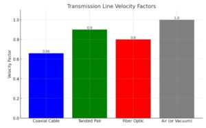
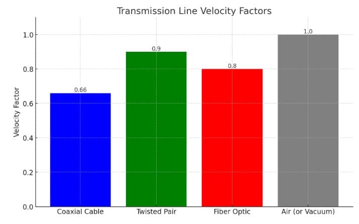
The graph above illustrates the concept of the Velocity Factor in various types of transmission lines, including Coaxial Cable, Twisted Pair, Fiber Optic, and Air (or Vacuum) as a reference. The Velocity Factor represents the speed at which an electromagnetic wave travels through the transmission line compared to the speed of light in a vacuum.
- Coaxial Cable: Shows a Velocity Factor of 0.66, indicating that signals travel at 66% of the speed of light in this medium.
- Twisted Pair: Has a Velocity Factor of 0.9, with signals traveling at 90% of the speed of light, making it faster than coaxial cable but still slower than in a vacuum.
- Fiber Optic: Demonstrates a Velocity Factor of 0.8, where signals travel at 80% of the speed of light. This is typically due to the refractive index of the glass or plastic used in the fiber.
- Air (or Vacuum): Represents the baseline with a Velocity Factor of 1.0, as electromagnetic waves travel at the speed of light in a vacuum.
The graph underscores the impact of the transmission medium on the propagation speed of electromagnetic waves, which is a critical factor in designing communication systems to ensure efficient signal transmission over distances.

