3. Measurements

Gear up for the 8.1.3 Measurements Practice Exam, an essential segment of the hamshack.ca QSL Advanced Amateur Radio course material. This targeted exam assesses your proficiency in various measurement techniques and tools crucial for any advanced-level amateur radio operator. The exam encompasses a variety of topics, which include:
- AC Measurements: Knowledge of alternating current characteristics such as peak, peak-to-peak, average, and RMS values.
- Power Measurements: Understanding of Peak Envelope Power (PEP), comparisons of PEP to average power, and calculations related to the voltage across the load.
- Radio Testing Equipment: Familiarity with the use of dip meters and signal generators in radio tuning and testing.
- Calibration and Frequency Measurement: Proficiency with crystal calibrators, marking generators, and frequency counters for accurate signal processing.
- Oscilloscope: Skills in using an oscilloscope for visualizing waveforms and signal analysis.
- Meters and Measurement Devices: Competence in utilizing meters, multimeters, and power meters for various electrical and radio frequency measurements.
Structured with 25 questions selected from a comprehensive pool, the 8.1.3 Measurements Practice Exam is designed to test and reinforce your understanding of these measurement concepts and tools. It allows multiple attempts, ensuring you can measure your progress and achieve a deep understanding of the content.

Meters, Multimeters, and Power Meters
This chapter delves into the intricate world of electrical measurement tools, focusing on meters, multimeters, and power meters – essential instruments in electrical and electronic work, particularly in ham radio operations. The chapter explores various aspects of these devices, including the principles behind extending the range of meters through shunt and series resistors, understanding the sensitivity of ammeters and voltmeters, and the practical applications of these tools in measuring current, voltage, and RF power. Each section not only explains the technical concepts but also provides real-world parallels and calculations to enhance understanding. This comprehensive exploration is designed to equip readers with the knowledge to effectively use these tools in various scenarios, ensuring accurate and reliable measurements, which are critical in both amateur and professional radio communication setups.

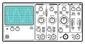
This chapter focuses on the usage of oscilloscopes in ham radio, an essential tool for visualizing and analyzing electronic signals. Oscilloscopes allow operators to observe the detailed waveform of signals, providing insights into frequency, amplitude, and phase characteristics. Understanding how to interpret oscilloscope readings is crucial for diagnosing equipment issues, aligning transmitters and receivers, and ensuring signal quality. This chapter covers various aspects of oscilloscopes, including reading Lissajous patterns, understanding the limitations of oscilloscope accuracy, improving frequency response, and using oscilloscopes for specific applications such as signal quality checks and phase difference measurements.

Crystal Calibrators, Marking Generators, and Frequency Counters
This chapter delves into the intricate world of crystal calibrators, marking generators, and frequency counters, vital tools in ham radio for ensuring precision and accuracy in frequency measurement and calibration. Crystal calibrators provide reliable frequency references, essential for verifying and adjusting the accuracy of radio equipment. Marking generators are instrumental in aligning and testing receivers, offering marker signals at specific frequencies. Frequency counters, with their ability to measure the frequency of electrical signals accurately, are crucial for maintaining compliance with allocated frequency bands and for effective communication in ham radio. Understanding these devices is key to mastering ham radio operations, as they collectively ensure that equipment is precisely tuned and functioning optimally.

Exploring Dip Meters and Signal Generators
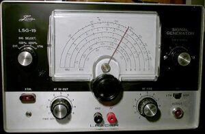
This chapter is dedicated to unraveling the complexities and utility of dip meters and signal generators, which are integral tools in the realm of ham radio and electronics. It begins by elucidating the concept of a dip meter, a variable frequency oscillator with a metered feedback current, and delves into its primary function of identifying resonant frequencies in circuits. Further, the chapter highlights the applications of dip meters in amateur radio stations, particularly in measuring resonant frequencies of antenna traps and various tuned circuits. Additionally, it introduces signal generators, characterizing them as high-stability oscillators that can produce a broad spectrum of frequencies and amplitudes, vital for electronic equipment testing and calibration. The understanding of these instruments is crucial for ham radio enthusiasts and electronic professionals in effectively measuring, testing, and tuning equipment to achieve optimal performance.

Transmitter Power and Measurements
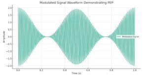
This chapter provides a focused examination of transmitter power and measurements, crucial for any amateur radio operator looking to advance their understanding and capabilities. We begin with the foundational concept of Peak-Envelope Power (PEP), exploring its significance in determining the maximum power output of transmissions. Through a progression from basic amplitude measurements to complex calculations of PEP under various conditions, the chapter aims to equip readers with the skills necessary for accurate power assessment and adjustment. It covers essential techniques for measuring voltage across dummy loads, converting peak-to-peak measurements to RMS values, and understanding the impact of these measurements on transmission quality and regulatory compliance. By the end of this chapter, operators will have a solid foundation in managing transmitter power efficiently, ensuring their transmissions are clear, effective, and within legal limits.

Understanding AC Measurements
This chapter introduces the foundational concepts of alternating current (AC) measurements, vital for anyone involved in electrical engineering or working with electronic devices. The focus is on understanding various amplitude dimensions of AC signals, such as peak, peak-to-peak, average, and RMS (Root Mean Square) values. These measurements are crucial for accurately analyzing and interpreting AC waveforms, especially when viewed through devices like oscilloscopes. The chapter also delves into how these measurements are used in practical applications, including the calibration of AC voltmeters and the application of Ohm’s law in AC circuits. By grasping these concepts, learners gain a comprehensive understanding of how AC voltages and currents are measured and interpreted, laying a foundation for more advanced studies in electronics and electrical systems.
