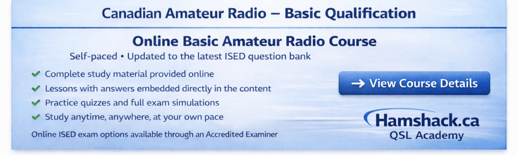
The new Course is updated to the latest official ISED Basic Question Bank and structured specifically to prepare students for the Canadian Amateur Radio Basic examination.
Hamshack.ca has served the Canadian amateur radio community since 2020, facilitating thousands of equipment sales and supporting new operators across the country. The QSL Academy Basic Course was developed by Don Rosberg, VE7DXE, and is built on real-world amateur radio operating experience combined with extensive experience creating structured online learning programs designed to make technical concepts clear and accessible.
The QSL Academy Basic course was developed to provide a structured, affordable pathway into amateur radio without the confusion often associated with traditional study materials.
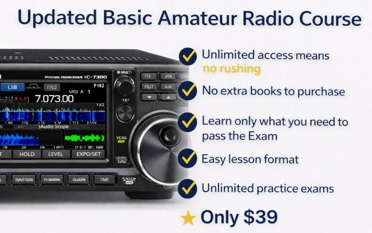
This comprehensive online course includes everything required to earn your Basic certification with confidence. All study material is provided online — no additional textbooks or outside materials are required — helping students save up to $100 compared to traditional classroom-based offerings.
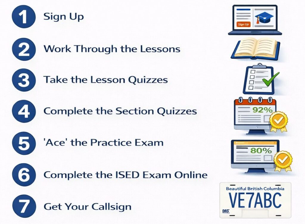
The course is fully self-contained — no extra books to buy, no deadlines, and no time pressure. Students progress at their own pace, confirming comprehension through lesson quizzes and section exams before attempting the full Practice Exam. When practice scores consistently reach 80% or higher, students are well prepared to schedule their official ISED Basic examination.
To simplify the licensing process, Hamshack.ca works directly with Gary Skett, VE7AS — an Accredited Examiner and experienced in-person course provider. Students may contact Gary to arrange the Basic examination online for a nominal fee of $20, making the final step toward licensing straightforward and accessible.

Straightforward Lesson Explanations
Answers Embedded Directly in the Lesson
Interactive Quizzes for Every Lesson
Final Exam Dry Runs
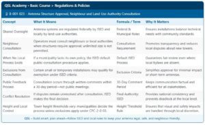
QSL Essentials Tables
Every lesson includes a quick-reference summary table highlighting the most important concepts. These tables are perfect for review, last-minute study, and exam-day preparation.
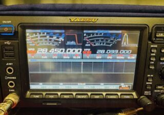
Real Ham Radio Gear Photos
Images from Hamshack.ca Buy & Sell listings help you recognize actual radios, antennas, and other equipment covered in lessons. This real-world connection makes the material more practical and memorable.
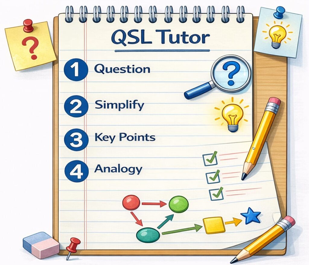
Introducing the QSL Tutor