
Start Here
FM Transmitter and Repeater Circuits
This chapter delves into the technical world of FM transmitters and repeater circuits, exploring key concepts and challenges in their operation and design. The focus is on understanding how various components and mechanisms work together to ensure clear and reliable FM communication. We begin by examining intermodulation interference, a common issue in repeater systems, where signals from different transmitters mix and create unwanted frequencies. The chapter then progresses to discuss the methods and technologies used to mitigate such interference, ensuring optimal performance of repeater stations. The intricate design of FM transmitters is also explored, highlighting how various circuits, like phase modulators and audio shaping networks, contribute to the generation and enhancement of FM signals. Additionally, the chapter addresses the specific requirements for filtering and isolation in repeater systems, essential for preventing signal interference and ensuring smooth operation. By diving into these technical aspects, the chapter aims to provide a comprehensive understanding of the complexities involved in FM transmitter and repeater circuit design and operation, crucial for anyone engaged in radio communication and broadcasting.
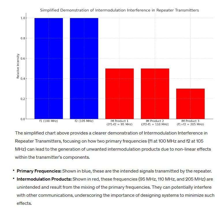
A-005-006-001: If the signals of two repeater transmitters mix together in one or both of their final amplifiers and unwanted signals at the sum and difference frequencies of the original signals are generated, what is this called?
Intermodulation Interference in Repeater Transmitters (A-005-006-001)
Understanding Intermodulation Interference: Question A-005-006-001 focuses on a phenomenon known as intermodulation interference, which occurs when signals from two repeater transmitters mix in their final amplifiers. This mixing generates unwanted signals at frequencies that are the sum and difference of the original signals. The answer is C. Intermodulation interference. This kind of interference is significant in radio communications because it can lead to additional, unwanted frequencies being transmitted, which can interfere with other communications. The situation is analogous to two musical instruments playing different notes together and inadvertently creating additional, unintended harmonies.
Parallels:
- Musical Harmonies: Like unintended harmonies from musical instruments, intermodulation interference creates additional frequencies in radio signals.
- Mixing Paint Colors: Just as mixing two paint colors can produce a third, unexpected color, intermodulation interference produces additional frequencies from the mixing of original signals.
Question Summary and Key Takeaways:
- Intermodulation Defined: Unwanted signals generated by mixing of two frequencies.
- Occurs in Final Amplifiers: Happens when signals from repeaters mix in their amplifiers.
- Can Cause Communication Disruption: Leads to transmission of unintended frequencies.
- Prevention is Key: Understanding and preventing it is essential in communication systems.
- Impacts System Design: Influences how repeater systems are designed and placed.
A-005-006-002: How does intermodulation interference between two repeater transmitters usually occur?
Causes of Intermodulation Interference (A-005-006-002)
Mechanism of Intermodulation in Repeaters: Question A-005-006-002 explores how intermodulation interference typically occurs between two close-proximity repeater transmitters. The answer, B. When they are in close proximity and the signals mix in one or both of their final amplifiers, emphasizes that physical proximity and signal mixing within the amplifiers are the primary causes. This situation is similar to when two closely positioned speakers play different songs, resulting in a jumbled sound due to the overlapping audio waves.
Parallels:
- Overlapping Speaker Audio: Like mixed music from nearby speakers, repeater signals can mix and create interference.
- Blending of Light Beams: Similar to overlapping light beams creating new colors, signal mixing in amplifiers produces new frequencies.
Question Summary and Key Takeaways:
- Proximity-Induced Mixing: Close location of transmitters leads to signal mixing.
- Occurs in Amplifiers: Signal mixing typically happens within the final amplifiers.
- Creates New Frequencies: Results in sum and difference frequency generation.
- Impacts Repeater Operation: Can disrupt normal repeater function.
- Needs Strategic Placement: Emphasizes the importance of strategic placement of repeater transmitters.
A-005-006-003: How can intermodulation interference between two repeater transmitters in close proximity often be reduced or eliminated?
Reducing Intermodulation Interference (A-005-006-003)
Mitigating Interference in Repeaters: Question A-005-006-003 deals with reducing or eliminating intermodulation interference between closely located repeaters. The solution, D. By installing a terminated circulator or ferrite isolator in the transmission line, involves using specific components to prevent the mixing of signals. These devices act like traffic controllers, ensuring that signals follow the correct path without interfering with each other. This is akin to using traffic lights to control vehicle flow at an intersection, preventing collisions and congestion.
Parallels:
- Traffic Light Control: Like traffic lights managing road intersections, circulators/isolators manage signal paths in repeaters.
- Water Flow in Pipes: Similar to valves controlling water flow to prevent backflow, these devices direct RF signals appropriately.
Question Summary and Key Takeaways:
- Use of Circulators/Isolators: Essential components for reducing interference.
- Prevent Signal Mixing: They help keep repeater signals separate.
- Improves System Reliability: Ensures clearer and more reliable communication.
- Technical Solution for a Common Problem: Represents a practical approach to a frequent issue in repeater systems.
- Essential in Repeater Design: Important consideration in the design and setup of repeater stations.
A-005-006-004: If a receiver tuned to 146.70 MHz receives an intermodulation product signal whenever a nearby transmitter transmits on 146.52, what are the two most likely frequencies for the other interfering signal?
Identifying Interfering Frequencies in FM Repeaters (A-005-006-004)
Detecting Intermodulation Frequencies: In Question A-005-006-004, the task is to identify the likely interfering frequencies causing intermodulation in an FM receiver scenario. The correct answer is D. 146.34 MHz and 146.61 MHz. This issue arises when a receiver tuned to 146.70 MHz picks up interference from a nearby transmitter at 146.52 MHz. The interfering signals are likely at frequencies equal to the sum and difference of the two original signals. This situation is analogous to the interference patterns created when two different sound waves meet and create beats or new tones.
Parallels:
- Sound Wave Interference: Similar to overlapping sound waves creating new tones, intermodulation produces new frequencies in radio signals.
- Ripples in Water: Like intersecting ripples in a pond creating new wave patterns, mixing radio frequencies generates additional signals.
Question Summary and Key Takeaways:
- Calculation of Interfering Frequencies: Sum and difference of original frequencies.
- Identification Based on Given Frequencies: Requires understanding of basic wave interaction principles.
- Important in Troubleshooting: Key for diagnosing interference issues in repeater systems.
- Impact on Receiver Performance: Can degrade the quality of received signals.
- Essential Knowledge for RF Engineers: Understanding this concept is crucial for designing and maintaining clear communication channels.
A-005-006-005: What type of circuit varies the tuning of an amplifier tank circuit to produce FM signals?
FM Transmitter Circuit for Signal Generation (A-005-006-005)
Phase Modulators in FM Transmitters: Question A-005-006-005 delves into the type of circuit used for tuning an amplifier tank circuit to produce FM signals. The correct answer is B. A phase modulator. A phase modulator varies the phase of the carrier wave relative to the modulating signal, which, in turn, results in frequency modulation. This process is akin to changing the direction of a moving car to alter its path – the phase modulator adjusts the direction (phase) of the carrier wave, thus changing its frequency.
Parallels:
- Steering a Car: Just like steering changes a car’s direction, a phase modulator alters the carrier wave’s phase to produce FM.
- Changing Course in Sailing: Similar to adjusting sails to change direction, a phase modulator shifts the phase for frequency modulation.
Question Summary and Key Takeaways:
- Phase Modulation for FM: Essential technique for generating FM signals.
- Adjusts Carrier Phase: Alters the phase of the carrier relative to the modulating signal.
- Results in Frequency Modulation: Changes in phase lead to changes in frequency.
- Fundamental in FM Transmitter Design: Critical for designing effective FM transmitters.
- Technical Insight into FM Generation: Demonstrates the intricate process of creating FM signals.
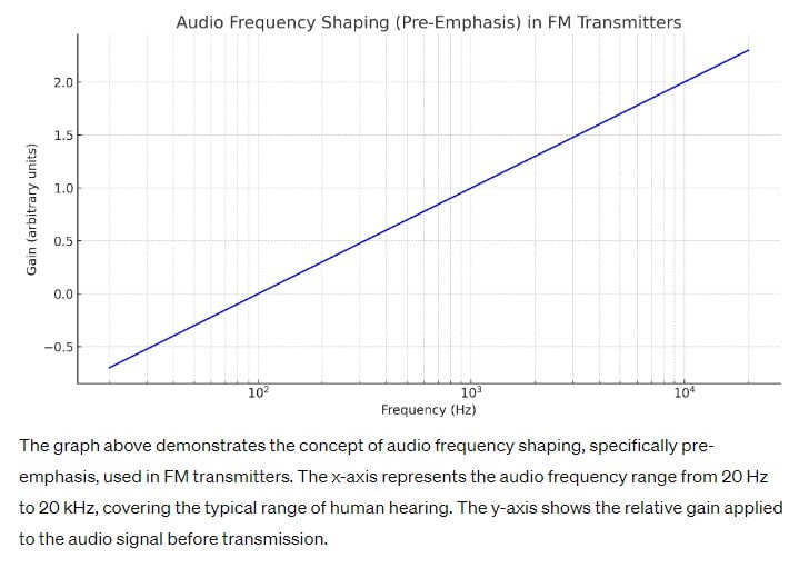
A-005-006-006: What audio shaping network is added at an FM transmitter to attenuate the lower audio frequencies?
Audio Frequency Shaping in FM Transmitters (A-005-006-006)
Implementing Pre-Emphasis in FM: Question A-005-006-006 asks about the audio shaping network added to FM transmitters to attenuate lower audio frequencies. The answer is B. A pre-emphasis network. This network boosts higher audio frequencies before transmission and reduces lower frequencies, improving the overall signal-to-noise ratio. It’s comparable to an audio engineer adjusting sound levels to enhance the clarity and quality of a music track.
Parallels:
- Audio Engineering: Like adjusting sound levels in music production, pre-emphasis shapes audio for clearer FM transmission.
- Photographic Filtering: Similar to using filters to emphasize certain colors in photography, pre-emphasis accentuates higher audio frequencies.
Question Summary and Key Takeaways:
- Function of Pre-Emphasis: Amplifies higher frequencies, attenuates lower ones.
- Improves Signal Quality: Enhances signal-to-noise ratio in FM transmission.
- Crucial in Broadcasting: Essential for maintaining high audio quality in FM radio.
- Standard Practice in FM: Widely implemented in FM transmitter systems.
- Technical Aspect of Audio Processing: Reflects the sophistication involved in audio transmission in FM.
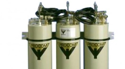
A-005-006-007: Which type of filter would be best to use in a 2-meter repeater duplexer?
Suitable Filters for Repeater Duplexers (A-005-006-007)
Choosing Filters for Repeaters: In Question A-005-006-007, the focus is on selecting the most appropriate type of filter for use in a 2-meter repeater duplexer. The answer, C. A cavity filter, highlights the effectiveness of cavity filters in providing good isolation between transmitting and receiving frequencies in repeater systems. This choice is similar to selecting a specific type of barrier or insulator in a physical system to prevent interference between two separate processes.
Parallels:
- Isolation in Electrical Circuits: Like using insulators to separate electrical circuits, cavity filters isolate transmitter and receiver frequencies.
- Soundproofing Between Rooms: Similar to soundproof barriers preventing noise leakage, cavity filters stop frequency interference in repeaters.
Question Summary and Key Takeaways:
- Cavity Filters in Duplexers: Ideal for separating transmit and receive frequencies.
- Provides Effective Isolation: Essential for preventing interference in repeaters.
- Choice Influences Repeater Performance: Directly affects the quality and clarity of communication.
- Key Component in Repeater Design: Critical in the design and setup of effective repeater systems.
- Reflects RF Engineering Principles: Demonstrates the practical application of RF engineering concepts.
A-005-006-008: The characteristic difference between a phase modulator and a frequency modulator is:
Difference Between Phase and Frequency Modulators (A-005-006-008)
Distinguishing Phase and Frequency Modulation: Question A-005-006-008 explores the key difference between phase modulators and frequency modulators. The answer, A. Pre-emphasis, indicates that pre-emphasis is a distinctive feature primarily associated with frequency modulation. Pre-emphasis is the process of amplifying higher audio frequencies before modulation, which enhances the overall audio quality in FM transmission. This concept can be likened to a graphic equalizer boosting certain frequencies to improve sound quality.
Parallels:
- Graphic Equalizer in Audio Systems: Like a graphic equalizer boosting high frequencies for clarity, pre-emphasis in FM improves audio quality.
- Accentuating Features in Photography: Similar to how a photographer enhances certain colors for effect, pre-emphasis accentuates higher audio frequencies in FM.
Question Summary and Key Takeaways:
- Pre-Emphasis in FM: Integral to frequency modulation for enhancing audio quality.
- Unique to FM: Differentiates frequency modulators from phase modulators.
- Improves Signal-to-Noise Ratio: Key for maintaining high audio fidelity in FM broadcasting.
- Technical Aspect of FM: Highlights the complexity involved in FM transmission.
- Essential for Broadcast Quality: Ensures that FM broadcasts have clear and crisp audio.
A-005-006-009: In most modern FM transmitters, to produce better sound, a compressor and a clipper are placed:
Sound Enhancement in Modern FM Transmitters (A-005-006-009)
Using Compressors and Clippers in FM Transmission: Question A-005-006-009 asks about the placement of compressors and clippers in modern FM transmitters to enhance sound quality. The correct answer is B. Between the audio amplifier and the modulator. These components are used to shape and optimize the audio signal before it modulates the carrier wave, similar to how a sculptor shapes clay before finalizing a sculpture.
Parallels:
- Sculpting Process: Like a sculptor refining clay before the final sculpture, compressors and clippers refine the audio before FM modulation.
- Editing a Manuscript: Similar to editing a manuscript before publishing, these components adjust the audio signal for optimal transmission.
Question Summary and Key Takeaways:
- Placement of Compressors and Clippers: Positioned between the audio amplifier and the modulator in FM transmitters.
- Enhance Audio Quality: They shape and optimize the audio signal for transmission.
- Crucial for Broadcast Clarity: Ensures the audio quality is maintained in FM broadcasting.
- Technical Aspect of FM Transmitters: Demonstrates the sophistication in FM transmitter design.
- Improves Listener Experience: Essential for delivering high-quality audio to FM radio listeners.
A-005-006-010: Three important parameters to be verified in an FM transmitter are:
Verifying FM Transmitter Performance (A-005-006-010)
Key Parameters in FM Transmitter Verification: Question A-005-006-010 focuses on the important parameters to verify in an FM transmitter. The answer, B. Power, frequency deviation, and frequency stability, underscores the critical aspects that ensure the transmitter’s proper functioning. These parameters are like the vital signs in a medical check-up, indicating the health and performance of the transmitter.
Parallels:
- Medical Check-Up: Just as vital signs are checked in a medical exam, these parameters indicate the health of an FM transmitter.
- Vehicle Inspection: Similar to inspecting a car’s engine, brakes, and tires, these checks ensure the transmitter’s optimal performance.
Question Summary and Key Takeaways:
- Power Output: Essential to measure and verify for effective transmission.
- Frequency Deviation: Indicates how accurately the transmitter adheres to assigned frequencies.
- Frequency Stability: Crucial for consistent and reliable transmission.
- Key for Regulatory Compliance: Ensures the transmitter operates within legal limits.
- Fundamental for Broadcast Quality: Impacts the overall quality and reach of FM broadcasting.
A-005-006-011: Intermodulation interference products are not typically associated with which of the following:
Passive Intermodulation and FM Transmitter Interference (A-005-006-011)
Understanding Passive Intermodulation: In Question A-005-006-011, the focus is on the association of passive intermodulation with intermodulation interference in FM transmitters. The correct answer, C. intermediate frequency stage, points out that passive intermodulation is not typically related to the intermodulation interference found in FM transmitter systems. Passive intermodulation is more relevant to passive components like cables and connectors, whereas intermodulation interference in transmitters is usually due to non-linear behavior in active components.
Parallels:
- Noise in Audio Equipment: Like passive intermodulation, unwanted noise in audio systems often arises from connections and cables, not the active components.
- Background Noise in Communication: Similar to passive interference, background noise can disrupt clear communication but is not the main concern in active transmission.
Question Summary and Key Takeaways:
- Passive Intermodulation Unrelated: Not a typical source of interference in FM transmitters.
- Focus on Active Components: Intermodulation interference more common in active parts of the transmitter.
- Differentiates Component Impact: Highlights the differing roles of passive and active components in RF systems.
- Implications for System Design: Guides the focus on minimizing non-linearities in active components.
- Essential Knowledge for Troubleshooting: Important for diagnosing and resolving transmission issues.
Insights into FM Transmitters and Repeater Circuits
Throughout this chapter, we explored the intricate workings of FM transmitters and repeater circuits, gaining insights into both their technical challenges and solutions. We began by understanding the phenomenon of intermodulation interference, its causes, and methods to mitigate it, emphasizing the importance of careful design and placement of repeater transmitters. The role of various circuit components in FM transmitters, such as phase modulators and audio shaping networks, was examined to understand how they contribute to signal quality and transmission efficiency. We also discussed the selection of appropriate filters for repeater duplexers, highlighting the significance of cavity filters in maintaining clear communication channels. Additionally, the chapter covered the differences between phase and frequency modulation techniques and the use of sound enhancement tools in modern FM transmitters. By addressing these aspects, the chapter provided valuable knowledge on effectively managing and optimizing FM transmission systems, making it an essential resource for professionals and enthusiasts in the field of radio communication.