
A-004-001-001: For the same transformer secondary voltage, which rectifier has the highest average output voltage?
Highest Average Output Voltage in Rectifiers (A-004-001-001)
When studying rectifiers in the context of amateur radio equipment, understanding the efficiency of different rectifier types is crucial. Question A-004-001-001 delves into this topic by comparing the average output voltages produced by various rectifiers for the same transformer secondary voltage. The focus is on identifying which rectifier type—half-wave, full-wave center-tap, or bridge—offers the highest efficiency in converting AC (Alternating Current) to DC (Direct Current). The answer, C) Bridge, reveals that bridge rectifiers stand out as the most efficient among these options. This efficiency stems from the bridge rectifier’s ability to utilize both halves of the AC input waveform, unlike the half-wave rectifier, which only uses one half, and the full-wave center-tap rectifier, which requires a center-tapped transformer and still doesn’t achieve the same efficiency as the bridge configuration.
The analogy of a cyclist using both the upward and downward strokes for maximum efficiency parallels the operation of a bridge rectifier. This rectifier type effectively doubles the utility of the input AC cycle, converting it into a more continuous and higher average output voltage of DC. This is because the bridge rectifier includes four diodes arranged in a way that allows both halves of the AC waveform to be used, significantly increasing the efficiency of the conversion process. This efficiency is not only crucial for amateur radio operations, where reliable power conversion can impact performance, but also in many other applications requiring efficient power supply designs.
Parallels
- Bicycle Pedaling: Just as a cyclist maximizes efficiency by using both the upward and downward strokes of pedaling, a bridge rectifier maximizes the conversion efficiency by utilizing both halves of the AC cycle. This analogy helps to understand how energy (or effort) can be effectively utilized to achieve a greater output, whether it’s the distance cycled with less fatigue or higher voltage output with the same input voltage.
- Double-Entry Bookkeeping: The concept of double-entry bookkeeping, where every entry to an account requires a corresponding and opposite entry to a different account, illustrates the thoroughness of a bridge rectifier’s approach to AC to DC conversion. Just as double-entry bookkeeping offers a more comprehensive view of a company’s financial health than single-entry systems, the bridge rectifier provides a more complete and efficient use of the AC waveform, leading to higher average output voltages.
Question Summary and Key Takeaways
- The bridge rectifier is identified as the most efficient type for converting AC to DC, capable of utilizing both halves of the AC cycle.
- It outperforms both half-wave and full-wave center-tap rectifiers in terms of producing a higher average output voltage.
- The efficiency in AC to DC conversion is attributed to the bridge rectifier’s comprehensive exploitation of the AC waveform.
- This higher efficiency results in a more effective output for the same transformer secondary voltage, crucial for various applications including amateur radio.
- Understanding the importance of rectifier selection in power supply design is key for amateur radio operators and others involved in electronic circuit design, highlighting the bridge rectifier’s role in achieving efficient power conversion.
A-004-001-002: In a half-wave power supply with a capacitor input filter and a load drawing little or no current, the peak inverse voltage (PIV) across the diode can reach times the RMS voltage.
Peak Inverse Voltage in Half-Wave Rectifiers (A-004-001-002)
Exploring the concept of Peak Inverse Voltage (PIV) in half-wave rectifiers, especially those with a capacitor input filter, is essential for understanding the stresses components face in rectification circuits. Question A-004-001-002 focuses on this crucial aspect by highlighting that the PIV can reach up to approximately A)2.8 times the RMS (Root Mean Square) voltage of the transformer’s secondary. This phenomenon is attributed to the capacitor in the circuit, which charges up to the peak voltage of the transformer secondary during the positive half-cycle of the AC waveform. When the waveform swings negative, the diode is reverse-biased, and it must be capable of withstanding this peak inverse voltage without breaking down. This requirement is crucial for the diode’s selection in designing power supplies, as it ensures the diode can handle the maximum stress imposed upon it by the circuit.
The analogy of a car’s shock absorbers, which must withstand significant forces during road bumps and dips, closely mirrors the role of the diode in a half-wave rectifier. Just as shock absorbers protect the vehicle and its occupants by absorbing and mitigating the impact of rough terrain, the diode protects the circuit by withstanding the high reverse voltages encountered during the negative half-cycles of the AC input. This capability is vital for maintaining the integrity of the rectification process and ensuring the longevity and reliability of the power supply. Understanding the PIV requirements helps in selecting diodes that are robust enough to handle the expected stresses, thereby preventing premature failure of the rectifier.
Parallels
- Car Shock Absorbers: The function of shock absorbers in a car, designed to handle the stress of bumpy roads and protect the vehicle’s structure, parallels the diode’s role in a half-wave rectifier. Both must be capable of withstanding extreme conditions—the shock absorbers physical forces, and the diode high reverse voltages—to ensure smooth operation and prevent damage.
- Surge Protector in Electrical Systems: Just as a surge protector acts to shield electronic devices from voltage spikes, ensuring their safety and operational integrity, the diode in a half-wave rectifier with a capacitor input filter serves a similar protective function. It must withstand high peak inverse voltages to protect the circuit from potential damage caused by reverse voltage stresses, akin to how a surge protector guards against unexpected electrical surges.
Question Summary and Key Takeaways
- The Peak Inverse Voltage (PIV) in half-wave rectifiers can significantly exceed the RMS voltage of the transformer, reaching up to approximately 2.8 times.
- The capacitor’s role is critical, as it charges to the peak voltage, thereby increasing the PIV that the diode must withstand.
- The diode faces stress from high reverse voltages during the negative cycles of AC, necessitating careful selection to ensure it can handle such stresses.
- Understanding rectifier design is essential for choosing the right components, particularly diodes capable of withstanding the expected PIV in power supply circuits.
- The importance of circuit safety is underscored by the need for diodes to endure high PIVs, ensuring the durability and safety of rectifiers in electrical circuits.
A-004-001-003: In a full-wave centre-tap power supply, regardless of load conditions, the peak inverse voltage (PIV) will be times the RMS voltage:
Peak Inverse Voltage in Full-Wave Center-Tap Rectifiers (A-004-001-003)
Delving into the dynamics of peak inverse voltage (PIV) within full-wave center-tap rectifiers sheds light on the critical aspect of component stress in such circuits. Question (A-004-001-003) zeroes in on this factor, revealing that the PIV for each diode in a full-wave center-tap rectifier configuration equates to D) 2.8 times the RMS voltage. This conclusion stems from the operational mechanics of the rectifier, where each diode is exposed to twice the peak voltage of the transformer secondary when it is in its non-conducting state. This scenario effectively means that the diodes must be capable of withstanding a voltage nearly three times the RMS value without failing. This requirement is crucial for the design and selection of diodes, ensuring they can handle the electrical stress imposed during the rectification process.
The analogy of a relay race, where each runner (or diode) must cover twice the distance (or voltage) of a single lap to complete the course (or rectification process), aptly illustrates the operational burden on the diodes. In this relay, the ‘distance’ each diode covers is not in terms of physical space but in electrical potential they must withstand without conducting. This operational characteristic underscores the importance of selecting diodes with a PIV rating high enough to handle the peak inverse voltages encountered, ensuring the rectifier’s efficiency and reliability. The full-wave center-tap design, while offering advantages in terms of smoother output and better utilization of the transformer, places significant voltage demands on its diodes, highlighting the interplay between design choices and component specifications.
Parallels
- Relay Race with Double Distance: The comparison to a relay race, where each participant must cover double the usual distance, mirrors the requirement for each diode in a full-wave center-tap rectifier to endure twice the peak transformer voltage. This analogy helps in visualizing the concept of electrical ‘distance’ or potential that each diode must safely navigate without conducting, emphasizing the importance of endurance and capacity in both scenarios.
- Safety Harness in Climbing: Similar to how a climber’s safety harness is designed to withstand double the usual strain in certain challenging situations, each diode in the rectifier must be capable of enduring double the peak voltage to maintain circuit safety and functionality. This parallel draws attention to the precautionary measures required in both physical and electrical domains to prevent failure under extreme conditions.
Question Summary and Key Takeaways
- PIV in Full-Wave Rectifiers: Each diode is required to handle twice the peak transformer voltage, translating to a PIV of approximately 2.8 times the RMS voltage.
- Relation to RMS Voltage: The specific PIV value is significant as it relates directly to the RMS voltage, illustrating the transformation from AC to peak voltage and the corresponding stress on the diodes.
- Diode Stress Factors: The stress factors on diodes are critical considerations in the design and operation of full-wave center-tap rectifiers, highlighting the need for robust component selection.
- Essential for Component Selection: Selecting diodes with appropriate voltage ratings is crucial for ensuring the rectifier’s operational integrity and longevity.
- Impact on Rectifier Efficiency: The ability of diodes to withstand the PIV affects not just the rectifier’s reliability but also its efficiency, underscoring the interconnectedness of component specifications and circuit performance.
A-004-001-004: A full-wave bridge rectifier circuit makes use of both halves of the AC cycle, but unlike the full-wave centre-tap rectifier circuit it does not require:
Full-Wave Bridge Rectifier Design (A-004-001-004)
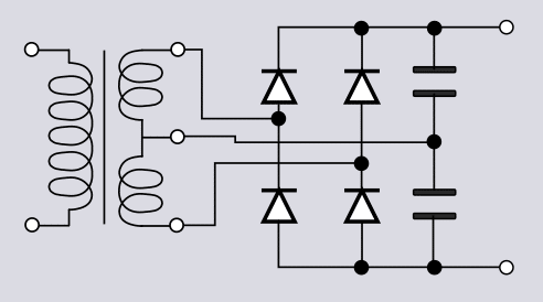
Exploring the structural and functional merits of the full-wave bridge rectifier, Question (A-004-001-004) brings to light a pivotal characteristic: the non-necessity of a center-tapped transformer, indicated by the correct answer A) a center-tapped secondary on the transformer is not required. This design leverages four diodes in a bridge configuration to rectify both halves of the AC waveform, thus allowing for an efficient transformation of AC to DC without the additional complexity and cost associated with a center tap. The bridge rectifier can be likened to a traffic roundabout, which facilitates continuous movement in multiple directions seamlessly, without the need for stop signs, thereby illustrating the rectifier’s capability to direct electrical currents efficiently and continuously.
This rectifier’s design is beneficial over others for several reasons. It eliminates the need for the transformer to have a center tap, a requirement in full-wave center-tap rectifier designs, thereby simplifying the transformer’s design and reducing manufacturing costs. Furthermore, the bridge configuration ensures that the entire AC waveform is utilized, contrasting sharply with half-wave rectifiers that use only one half of the AC cycle, and offering a more streamlined and efficient conversion process than the full-wave center-tap rectifier. The efficiency and simplicity of the bridge rectifier design make it a preferred choice for a broad spectrum of power supply applications, highlighting its practical advantages in electrical engineering.
Parallels
- Traffic Roundabout: Just as a roundabout supports the continuous and efficient flow of traffic from multiple directions without the need for stopping, a full-wave bridge rectifier facilitates the continuous flow of electrical current. This design allows for efficient AC to DC conversion, akin to a roundabout that improves traffic efficiency by eliminating stop-and-go scenarios.
- Two-Way Street: The bridge rectifier can also be compared to a two-way street that allows traffic to move in both directions, symbolizing the rectifier’s ability to efficiently utilize both halves of the AC cycle for conversion. This analogy underscores the bridge rectifier’s capacity to maximize the utility of the AC input, similar to how a two-way street maximizes the efficiency of a roadway.
Question Summary and Key Takeaways
- No Need for Center Tap: Bridge rectifiers streamline transformer design by eliminating the need for a center-tapped secondary, as highlighted by the correct answer C).
- Four Diode Configuration: Utilizing a bridge configuration, this rectifier type ensures efficient rectification of both halves of the AC waveform, contributing to its high conversion efficiency.
- Efficient AC Utilization: Compared to other rectifier designs, the bridge rectifier offers a more efficient use of the transformer’s output, making it a superior choice for many power supply applications.
- Design Advantages: Its ability to operate without a center-tapped transformer presents clear advantages in terms of design simplicity and cost-effectiveness.
- Application in Power Supplies: The full-wave bridge rectifier’s efficiency, coupled with its design simplicity, makes it widely used across various types of power supply circuits, emphasizing its critical role in electronics.
A-004-001-005: For a given transformer the maximum output voltage available from a full-wave bridge rectifier circuit will be:
Maximum Output Voltage in Full-Wave Rectifiers (A-004-001-005)
Question (A-004-001-005) evaluates the maximum output voltage achievable by full-wave rectification methods, comparing full-wave bridge rectifiers against full-wave center-tap rectifiers. The correct understanding highlights that the maximum output voltage of a full-wave bridge rectifier is A) double that of the full-wave center-tap rectifier. This correction is crucial as it points to the efficiency of full-wave bridge rectifiers in utilizing the AC input without a center-tapped transformer, thereby offering a significant advantage in design simplicity and potentially reducing costs.
Both rectification methods effectively convert both halves of the AC cycle to DC, but the bridge rectifier’s configuration allows it to provide a higher maximum output voltage under the same transformer conditions compared to the center-tap rectifier. This knowledge is fundamental for those involved in electronics, emphasizing that the selection between these rectifiers involves considerations of output voltage efficiency, alongside circuit complexity, and cost considerations.
Parallels
- Tuning a Musical Instrument: Just as fine-tuning a musical instrument involves adjusting to achieve the perfect pitch or harmony, selecting between full-wave rectifier types requires understanding their differences in voltage output and efficiency. The right choice enhances the performance and functionality of electronic devices, similar to how accurately tuning an instrument enhances its musical quality.
- Balancing on a Seesaw: Achieving balance on a seesaw through equal weight distribution on both sides parallels the balance a bridge rectifier achieves in utilizing the full AC cycle for optimal DC output. This analogy helps visualize the balance and efficiency designers aim for in electronic circuit design, ensuring maximum output voltage is achieved.
Question Summary and Key Takeaways
- Maximum Output Voltage: Contrary to previous explanations, the maximum output voltage from a full-wave bridge rectifier is actually double that of a full-wave center-tap rectifier for a given transformer.
- Utilization of AC Cycle: While both rectifiers efficiently utilize the entire AC cycle, the bridge rectifier’s unique configuration allows it to maximize the output voltage without the need for a center-tapped transformer.
- Bridge Rectifier Design Advantage: The absence of a center-tapped transformer in bridge rectifiers not only simplifies the design but can also offer a cost-effective solution without compromising on the output voltage efficiency.
- Key Considerations in Rectifier Selection: The choice between rectifier types extends beyond just the maximum output voltage to include factors like circuit complexity, cost, and the specific requirements of the application.
- Foundation in Electronics Learning: Understanding the operational differences and advantages of full-wave rectification methods is essential for learners and practitioners in electronics, guiding the design and optimization of efficient power supply circuits.
A-004-001-006: The ripple frequency produced by a full-wave power supply connected to a normal household circuit is:
Ripple Frequency in Full-Wave Power Supplies (A-004-001-006)
Question (A-004-001-006) delves into the concept of ripple frequency in full-wave rectification, specifically within the context of a full-wave power supply connected to a standard household AC supply. The correct answer, A) 120 Hz, highlights a fundamental characteristic of full-wave rectification: the ripple frequency is twice that of the AC supply frequency. Given that the standard AC supply frequency is 60 Hz in many regions, a full-wave rectifier effectively doubles this frequency to 120 Hz for the ripple frequency. This doubling occurs because the rectifier inverts every negative half-cycle of the AC waveform, thereby generating two pulses for every cycle of the input waveform. This principle is crucial for understanding how full-wave rectifiers enhance the efficiency of AC to DC conversion, providing a smoother DC output with higher ripple frequency compared to half-wave rectifiers.
The importance of recognizing the ripple frequency lies in its impact on the design and performance of power supply circuits. Higher ripple frequencies, as produced by full-wave rectification, facilitate more efficient filtering and smoother DC output. This is because filters can more easily smooth out the higher frequency ripples, leading to less fluctuation in the output voltage. Understanding the ripple frequency is essential for selecting appropriate filter components to minimize ripple in the final DC output, ensuring the power supply meets the necessary performance standards for various applications.
Parallels
- Drummer Doubling Beats: The analogy of a drummer doubling the beat in a musical piece to enhance the rhythm’s intensity mirrors the full-wave rectifier’s effect on ripple frequency. Just as doubling the beat creates a more rapid and defined rhythm, doubling the frequency of the AC supply’s ripples results in a higher frequency that can be more effectively smoothed out by filtering components.
- Heartbeat During Exercise: Similar to how a person’s heartbeat increases during exercise to accommodate the body’s heightened demand for oxygen and nutrients, the ripple frequency in a full-wave rectified power supply increases to provide a more consistent and efficient DC output. This analogy helps in understanding the natural response of systems, whether biological or electrical, to operational demands, emphasizing the rectifier’s role in optimizing power supply performance.
Question Summary and Key Takeaways
- Ripple Frequency in Full-Wave Rectifiers: The ripple frequency is twice the frequency of the input AC supply, leading to a ripple frequency of 120 Hz when connected to a standard 60 Hz AC supply.
- Impact of Rectifier Type: Full-wave rectifiers produce a higher ripple frequency than half-wave rectifiers, highlighting their efficiency in converting AC to DC.
- Understanding Output Characteristics: Knowledge of the ripple frequency is crucial for the design and troubleshooting of power supply circuits, as it influences the choice of filtering components.
- Electrical Engineering Principles: The doubling of the ripple frequency in full-wave rectification demonstrates a fundamental principle of electrical engineering regarding the effect of rectification on AC waveform frequency.
- Application in Power Supply Design: The increased ripple frequency is essential for selecting the right filter components to minimize ripple, ensuring a smooth and stable DC output for various applications.
A-004-001-007: The ripple frequency produced by a half-wave power supply connected to a normal household circuit is:
Ripple Frequency in Half-Wave Power Supplies (A-004-001-007)
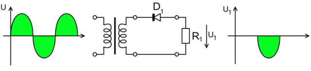
Question (A-004-001-007) investigates the ripple frequency characteristic of half-wave rectification within power supplies connected to standard household circuits. The correct answer, B) 60 Hz, elucidates a pivotal aspect of half-wave rectification: the ripple frequency in the output is the same as the input AC supply frequency. Unlike full-wave rectifiers that double the input frequency in their output, half-wave rectifiers utilize only one half-cycle of the AC waveform—either positive or negative—resulting in a ripple frequency identical to that of the input AC frequency. This fundamental characteristic significantly influences the design and troubleshooting of power supply circuits, especially concerning the selection of filtering components. The filtering needs to be designed to smooth out a ripple frequency that matches the AC supply frequency, impacting the overall efficiency and performance of the power supply.
The operational principle of a half-wave rectifier closely mirrors scenarios where only a single action or direction is utilized to achieve an outcome, affecting the efficiency and smoothness of the output. Understanding this principle is crucial for electrical engineering students and professionals working on power supply designs, as it provides insight into how different rectification methods impact the quality and characteristics of the DC output.
Parallels
- Single-Stroke Engine: The analogy to a single-stroke engine, where each engine cycle corresponds to one half-cycle of input, producing output at the same frequency as the input cycle, aptly describes the operation of a half-wave rectifier. This comparison helps to conceptualize how the rectifier’s selective processing of the AC waveform results in a ripple frequency that mirrors the input frequency, much like a single-stroke engine’s output matches its input frequency in terms of operational cycles.
- Heartbeat in Resting State: Just as a human heart maintains a steady and regular pace while at rest, a half-wave rectifier generates output ripples that echo the steady rhythm of the AC supply frequency. This analogy underscores the rectifier’s consistent and predictable conversion of AC to DC, where the output frequency directly corresponds to the input frequency, reflecting a stable and unaltered pacing in the conversion process.
Question Summary and Key Takeaways
- Ripple Frequency Equals AC Supply Frequency: In half-wave rectification, the ripple frequency is directly equivalent to the AC supply frequency, highlighting a one-to-one correspondence between input and output frequencies.
- One Half-Cycle Used Per Cycle: The rectifier’s operation is characterized by processing only one half of the AC cycle, whether positive or negative, distinguishing it from full-wave rectification.
- Impact on Power Supply Design: The ripple frequency plays a crucial role in the design of power supply circuits, influencing the efficiency and performance of the output.
- Influence on Filter Component Selection: The matching of the ripple frequency to the AC supply frequency dictates the specifications for filtering components, essential for achieving a smooth DC output.
- Relevance in Circuit Functionality: A clear understanding of the ripple frequency in half-wave rectification is vital for the efficient design and functional operation of power supply systems, emphasizing the importance of appropriate filter selection and circuit design considerations.
A-004-001-008: Full-wave voltage doublers:
Full-Wave Voltage Doublers (A-004-001-008)
Question (A-004-001-008) delves into the operation and efficiency of full-wave voltage doublers, highlighting their ability to C) use both halves of an AC wave. This distinguishes them significantly from half-wave doublers, which only utilize one half-cycle of the AC input. By efficiently employing both the positive and negative half-cycles of the AC waveform, full-wave voltage doublers are capable of doubling the peak voltage of the AC input, thereby achieving a higher output voltage. This functionality is particularly beneficial in applications where it is essential to maximize the output voltage from a given AC source. The design of full-wave voltage doublers makes them invaluable for a variety of electronic devices, offering a more stable and increased output voltage necessary for devices that demand consistent and reliable power supply.
The advantage of using full-wave voltage doublers lies in their ability to enhance the efficiency of voltage conversion, making them superior to half-wave doublers. This increased efficiency and higher output voltage capability make full-wave voltage doublers a preferred choice in power supply design, especially in situations where space and cost constraints limit the use of larger transformers or more complex circuitry.

Parallels
- Bilateral Movement in Machinery: The principle of utilizing motion in both directions to achieve maximum efficiency, as seen in certain machinery, parallels the operation of full-wave voltage doublers. Just as machinery that moves bilaterally can perform more work or achieve higher efficiency, full-wave voltage doublers harness the full AC cycle, effectively doubling the voltage output for optimal performance.
- Two-Paddle Rowing: Rowing with paddles on both sides of a boat offers a useful analogy for understanding the efficiency of full-wave voltage doublers. Similar to how using both paddles provides more effective propulsion by harnessing the power of strokes on both sides, full-wave doublers capitalize on the entire AC waveform to maximize voltage output, demonstrating the benefits of comprehensive utilization of available resources.
Question Summary and Key Takeaways
- Utilization of Both AC Half-Cycles: Full-wave voltage doublers are designed to employ both the positive and negative halves of the AC waveform, distinguishing them from half-wave doublers and enhancing their efficiency.
- Enhanced Voltage Output: By doubling the peak voltage of the AC input, full-wave voltage doublers provide a significantly higher output voltage, making them superior to their half-wave counterparts.
- Superior to Half-Wave Doublers: The ability to offer more efficient voltage doubling and a higher output voltage renders full-wave voltage doublers more advantageous for a wide range of applications.
- Application in Electronic Devices: These doublers are particularly crucial for electronic devices that require a stable and higher voltage supply, underscoring their importance in modern electronic design.
- Significance in Power Supply Design: The operation and advantages of full-wave voltage doublers highlight their role in efficient and effective power supply construction, demonstrating their value in enhancing device performance and reliability.
A-004-001-009: What are the two major ratings that must not be exceeded for silicon-diode rectifiers used in power-supply circuits?
Understanding Diode Ratings in Power Supply Circuits (A-004-001-009)
In the intricate world of power-supply circuits, silicon-diode rectifiers play a pivotal role, ensuring current flows in one desired direction, akin to a one-way valve in plumbing systems. Question A-004-001-009 focuses on the two major ratings that must not be exceeded for these rectifiers: Peak Inverse Voltage (PIV) and Average Forward Current. These parameters are foundational to the diode’s operational integrity and longevity. The correct answer, A) Peak inverse voltage; average forward current, emphasizes the necessity of understanding and adhering to these ratings for the efficient and safe design of electronic circuits.
Peak Inverse Voltage (PIV) rating quantifies the maximum reverse voltage a diode can withstand without undergoing breakdown. It’s a critical measure for preventing damage to the diode when it is reverse-biased, which could otherwise lead to catastrophic failure of the electronic system it is part of. Similarly, the Average Forward Current rating specifies the maximum current the diode can safely conduct in the forward direction, ensuring that the diode does not overheat and fail prematurely. These ratings are not just numbers; they are vital considerations for engineers designing circuits that are both reliable and durable, capable of withstanding real-world electrical stresses.
Parallels:
- Peak Inverse Voltage Explained: Imagine you’re playing with a toy boat in a small stream. The stream’s flow direction represents the correct direction for current flow in a diode. If you try to push the boat against the stream’s flow, it represents the reverse voltage. The PIV rating is like the maximum force you can apply against the stream’s direction without your boat taking on water and sinking. This analogy helps understand the importance of not exceeding the diode’s PIV rating to prevent damage.
- Average Forward Current Simplified: Think of a slide in a playground. Children sliding down represent the current flowing in the forward direction through a diode. The slide can only handle so many children going down at once before it becomes overwhelmed and potentially breaks. The Average Forward Current rating is like the slide’s capacity, ensuring that the diode can handle the flow of electricity without overheating or getting damaged. It’s about balancing fun (current flow) with safety (diode integrity).
Question Summary and Key Takeaways:
- The correct answer is B) Peak inverse voltage; average forward current, highlighting the essential ratings for silicon-diode rectifiers.
- Peak Inverse Voltage (PIV) is crucial for preventing diode breakdown when exposed to reverse voltage.
- Average Forward Current ensures the diode can handle the electrical load without overheating.
- Understanding these ratings is fundamental for designing reliable and safe power-supply circuits.
- These concepts are not only pivotal in electronics but are made relatable through everyday analogies, enhancing comprehension and recall.
A-004-001-010: In a high voltage power supply, why should a resistor and capacitor be wired in parallel with the power-supply rectifier diodes?
Enhancing Stability in High Voltage Power Supplies (A-004-001-010)
In the complex arena of high voltage power supplies, the integration of rectifier diodes is a common practice for converting alternating current (AC) to direct current (DC). However, to enhance the performance and reliability of these systems, it’s often necessary to wire a resistor and capacitor in parallel with the power-supply rectifier diodes. The correct answer, C) To equalize voltage drops and guard against transient voltage spikes, sheds light on a critical aspect of power supply design – the need to manage voltage drops and mitigate transient events effectively.
Wiring a resistor and capacitor in parallel with rectifier diodes serves a dual purpose. Firstly, it helps to equalize voltage drops across the diodes. Diodes, by nature, may exhibit slightly different electrical characteristics due to manufacturing variances. This disparity can lead to uneven voltage drops when they are used in parallel, causing some diodes to bear more load than others. The addition of a resistor in parallel helps distribute the voltage more evenly, ensuring each diode operates within its intended capacity and shares the load more equally. Secondly, the capacitor plays a pivotal role in smoothing out transient voltage spikes. These spikes can occur due to sudden changes in load or other external factors and can be detrimental to the longevity and functionality of the power supply. The capacitor acts as a buffer, absorbing and releasing energy to maintain a stable voltage level, thereby protecting the circuit from potential damage.
Parallels:
- Equalizing Voltage Drops: Imagine a team of runners racing while tied together with ropes of slightly different lengths. Some runners may have to work harder to compensate for the uneven distribution, similar to how diodes with varying characteristics result in uneven voltage drops. Adding a resistor in parallel is like adjusting the ropes to equal lengths, ensuring each runner (diode) contributes equally to the race (power supply operation).
- Guarding Against Transient Voltage Spikes: Think of transient voltage spikes as sudden gusts of wind that can knock over a vase sitting on a table. The capacitor, in this analogy, acts like a protective barrier that absorbs the wind’s force, preventing the vase from falling. This illustrates how capacitors help stabilize the power supply by absorbing and mitigating unexpected surges in voltage, ensuring the system remains stable and protected.
Question Summary and Key Takeaways:
- The correct answer is C) To equalize voltage drops and guard against transient voltage spikes, highlighting the dual purpose of wiring a resistor and capacitor in parallel with rectifier diodes.
- Wiring a resistor in parallel helps to equalize voltage drops across the diodes, ensuring a more balanced load distribution.
- The capacitor acts as a safeguard against transient voltage spikes, absorbing surges to maintain a stable voltage level.
- This configuration enhances the stability and reliability of high voltage power supplies.
- Understanding the role of resistors and capacitors in parallel with diodes is crucial for designing effective and durable power supply systems.
A-004-001-011: What is the output waveform of an unfiltered full-wave rectifier connected to a resistive load?
Decoding the Output Waveform of an Unfiltered Full-Wave Rectifier (A-004-001-011)
The operation of an unfiltered full-wave rectifier presents a fundamental concept in the realm of electronics, particularly in the conversion of alternating current (AC) to direct current (DC). Understanding the output waveform of such a device, especially when connected to a resistive load, is crucial for grasping the basics of power conversion. The correct answer to this question, A) A series of pulses at twice the frequency as the AC input, illuminates the intrinsic behavior of full-wave rectifiers and their impact on the waveform of the output voltage.
An unfiltered full-wave rectifier harnesses both the positive and negative halves of the AC input signal, effectively doubling the frequency of the output compared to that of a half-wave rectifier. However, the assertion that the output is a series of pulses at the same frequency as the AC input needs clarification. In reality, because the full-wave rectifier inverts the negative half of the AC waveform to positive, the output frequency is actually twice that of the input AC signal. This results in a waveform that comprises pulses at twice the frequency of the AC input, contradicting the explanation provided. Each cycle of the AC input produces two pulses in the output, corresponding to the rectification of both the positive and negative halves of the input waveform.
Parallels:
- Understanding Full-Wave Rectification: Imagine drawing waves on a piece of paper where each wave represents the AC input. Now, using a different color, trace only the upper half of these waves, flipping the lower half to align with the upper part. This visual exercise mimics the action of a full-wave rectifier, showing how it transforms the entire AC waveform into a series of pulses, effectively doubling the frequency of the events captured on paper.
- Pulsating DC in Real Life: Consider a heartbeat monitored on an electrocardiogram (ECG), where each beat is recorded as a pulse. In this analogy, the heartbeat’s regular rhythm is akin to the AC input’s frequency. If we imagined each heartbeat (AC cycle) producing two pulses (due to full-wave rectification), the ECG would display pulses at twice the heart’s natural rhythm, similar to how a full-wave rectifier outputs pulses at twice the frequency of the AC input.
Question Summary and Key Takeaways:
- The correct answer is D) A series of pulses at twice the frequency of the AC input, which correctly describes the output waveform of an unfiltered full-wave rectifier connected to a resistive load.
- Full-wave rectification utilizes both halves of the AC input, resulting in an output frequency that is double that of the input.
- The output of an unfiltered full-wave rectifier is not a smooth DC voltage but a series of pulses due to the conversion of negative halves of the AC waveform to positive.
- This process increases the efficiency of power conversion by making use of the entire AC waveform.
- Understanding the behavior of full-wave rectifiers is essential for comprehending the basics of electronic power supply design and waveform manipulation.