help support hamshack.ca...

QRP Z-Match Manual Antenna Tuner 3-28 MHz for HAM Radio
$67.02 (as of July 26, 2024 21:34 GMT -07:00 - More infoProduct prices and availability are accurate as of the date/time indicated and are subject to change. Any price and availability information displayed on [relevant Amazon Site(s), as applicable] at the time of purchase will apply to the purchase of this product.)
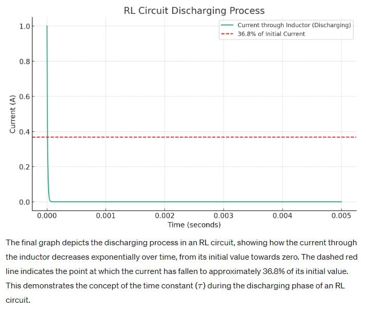
A-001-001-001: What is the meaning of the term “time constant” in an RL circuit?
Understanding the Time Constant in RL Circuits
The term “time constant,” denoted by τ (tau), plays a crucial role in the realm of electrical circuits, more so within the specific context of amateur radio and RF engineering. In an RL circuit, the time constant τ is fundamentally the period required for the current to ascend to 63.2% of its eventual maximum value upon the application of voltage. This definition, aligning with the correct answer D, underscores the intrinsic behavior of inductors in resisting immediate changes in current flow, thereby dictating the circuit’s response time to electrical inputs.
The time constant offers a quantifiable measure of how swiftly an RL circuit can adapt to changes, directly influencing its functionality in real-world applications such as signal processing and frequency modulation in amateur radio. The principle of inductive reactance, inherent to inductors, showcases the natural tendency of these components to oppose abrupt alterations in current, a phenomenon meticulously captured by the concept of the time constant. This understanding is not only pivotal for circuit design and analysis but also enriches the practical skills of amateur radio operators, enabling them to optimize their equipment for superior performance.
Parallels:
- Filling a Balloon: Consider the process of inflating a balloon. Just as the balloon gradually expands to accommodate more air, an inductor in an RL circuit gradually allows more current to flow through, reaching 63.2% of its full capacity in a span defined by the time constant.
- Heating a Room: Similar to how a heater takes time to warm a room, an RL circuit needs time to reach a certain level of current flow. The time constant τ is akin to the period required for the room’s temperature to reach a certain percentage of its target warmth, illustrating the gradual adaptation to new conditions.
Question Summary and Key Takeaways:
- The time constant in an RL circuit is defined as the time it takes for the current to reach 63.2% of its maximum value.
- This concept illustrates the inductor’s natural opposition to sudden changes in current, embodying the circuit’s transient response.
- Understanding time constants is essential for designing and analyzing circuits in amateur radio, affecting signal processing and frequency modulation.
- The time constant provides a measurable framework for predicting how quickly an RL circuit can respond to electrical stimuli.
- This knowledge enhances the practical abilities of amateur radio operators, allowing for the optimization of radio equipment and systems.
help support hamshack.ca...

Automatic Keyer Aluminum Controller MXK2 for Ham Radio Amplifier Potentiometer Board with Advanced Functionality for Ham Radio Enthusiasts
$31.02 (as of July 26, 2024 06:04 GMT -07:00 - More infoProduct prices and availability are accurate as of the date/time indicated and are subject to change. Any price and availability information displayed on [relevant Amazon Site(s), as applicable] at the time of purchase will apply to the purchase of this product.)A-001-002: What is the term for the time required for the capacitor in an RC circuit to be charged to 63.2% of the supply voltage?
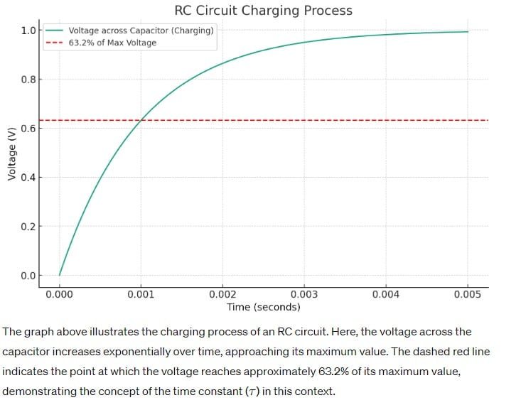
The Dynamics of Capacitive Charging
In the exploration of RC circuits, understanding the process and significance of a capacitor charging to 63.2% of the supply voltage is fundamental, encapsulated in the correct answer C as “One time constant.” This period, crucial for amateur radio operators, reflects the capacitor’s ability to store and release energy, which is paramount in tuning circuits, filtering signals, and managing power supply fluctuations in radio communication systems. The time constant in this context offers insight into the capacitor’s response time to changes in voltage, highlighting its role in conditioning signals for optimal transmission and reception.
The concept of the time constant in RC circuits serves as a predictive tool for engineers and hobbyists alike, enabling the design of circuits that meet specific operational criteria, such as timing delays or signal smoothing. The ability to calculate and apply the time constant ensures that capacitors are effectively utilized to stabilize voltage and filter noise, enhancing the clarity and reliability of amateur radio communications. This foundational knowledge is instrumental in advancing from basic to advanced proficiency in amateur radio licensure, underscoring the practical importance of electrical theory in the hobby.
Parallels:
- Filling a Pool with a Hose: Imagine using a garden hose to fill a swimming pool. The time it takes for the water level to reach a certain point—say, 63.2% of the pool’s capacity—can be likened to the capacitor charging through one time constant. This analogy helps illustrate the gradual nature of capacitive charging in response to applied voltage.
- Sunrise and the Day’s Warm-Up: Consider the way morning sunlight gradually warms the earth. The time from dawn until the temperature reaches a certain comfortable percentage of its peak daytime warmth mirrors the capacitor’s charging process to 63.2% of its maximum voltage, emphasizing the gradual accumulation of energy over time.
Question Summary and Key Takeaways:
- One time constant in an RC circuit is the time taken for a capacitor to charge to 63.2% of the supply voltage, illustrating the capacitor’s energy storage dynamics.
- This concept is crucial for signal filtering, timing circuits, and power management in amateur radio systems.
- The time constant acts as a predictive measure for designing circuits with specific response characteristics.
- Capacitors play a key role in voltage stabilization and noise filtering, contributing to the effectiveness of radio communication.
- Grasping the principles of capacitive charging and discharging is vital for those aiming to advance their understanding and practice in amateur radio.
A-001-003: What is the term for the time required for the current in an RL circuit to build up to 63.2% of the maximum value?
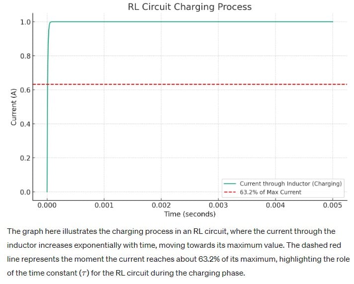
Navigating Current Growth in RL Circuits
This question focuses on identifying the period during which the current in an RL (Resistor-Inductor) circuit reaches 63.2% of its maximum value following the application of an external voltage source. The correct answer is B) One time constant, which is pivotal for understanding the dynamic behavior of inductive circuits in the field of amateur radio. This concept, denoted by the Greek letter τ (tau), encapsulates the inductor’s natural response to a change in current, offering insights into the circuit’s temporal response characteristics.
The significance of the time constant in RL circuits extends beyond theoretical knowledge, impacting practical applications such as the design of filters, timers, and signal modulators used in amateur radio equipment. A firm grasp of how quickly an inductor allows current to increase to a substantial fraction of its maximum value is essential for creating circuits that respond appropriately to operational demands. This understanding ensures that amateur radio operators can optimize the performance of their equipment, enhancing signal quality and communication reliability.
Parallels:
- Accelerating a Car: Imagine the process of accelerating a car from a standstill. Just as a car takes time to reach a certain speed, an RL circuit needs time for the current to build up to 63.2% of its maximum value. This analogy helps illustrate the gradual increase in current through an inductor, akin to the car’s acceleration.
- Plant Growth: Consider how a seedling grows over time. It doesn’t reach its full height instantly but gradually increases in size. Similarly, the current in an RL circuit doesn’t reach its maximum immediately but grows steadily, reaching 63.2% of its maximum at a rate defined by the time constant. This natural comparison highlights the concept of incremental change over time.
Question Summary and Key Takeaways:
- The term for the time required for the current in an RL circuit to reach 63.2% of its maximum value is known as one time constant.
- Understanding the time constant in RL circuits is crucial for designing and analyzing circuits in amateur radio, particularly for applications involving signal modulation and filtering.
- The time constant provides a measure of how quickly a circuit responds to changes, essential for optimizing the functionality and efficiency of radio communications equipment.
- This concept illustrates the inductive circuit’s transient response to electrical stimuli, emphasizing the gradual adaptation of current flow.
- Mastery of RL circuit dynamics, including time constant calculations, is vital for advancing the technical expertise of amateur radio operators.
A-001-004: What is the term for the time it takes for a charged capacitor in an RC circuit to discharge to 36.8% of its initial value of stored charge?
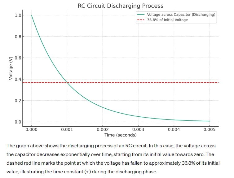
Unraveling Capacitor Discharge Dynamics
This question zeroes in on a key aspect of capacitor behavior in RC circuits, specifically the duration required for a charged capacitor to reduce its stored charge to 36.8% of its initial value. The correct answer A) One time constant reveals an essential principle of capacitor discharge, mirroring the charging process but in reverse. This period is critical for understanding how energy stored in a capacitor is released over time, impacting the performance of circuits in filtering, timing, and signal modulation applications within the amateur radio domain.
Capacitors play a pivotal role in amateur radio circuits, acting as temporary storage devices for electrical energy. The discharge process, characterized by the time constant, is fundamental to the operation of pulse-generating circuits, audio filters, and other electronic components that rely on precise timing and control of electrical signals. Knowledge of how quickly a capacitor discharges to a specific percentage of its stored charge is invaluable for designing circuits that require a predictable response to changes in electrical conditions, ensuring reliability and efficiency in amateur radio communications.
Parallels:
- Deflating a Balloon: Just as a balloon slowly releases air until it reaches a significantly lower volume, a charged capacitor discharges over time. The moment it reaches 36.8% of its initial charge corresponds to the time constant, analogous to the balloon having just enough air left to be considered partially inflated.
- Cooling a Hot Beverage: Imagine a hot beverage cooling down to 36.8% of its initial temperature. This cooling process can be likened to the discharge of a capacitor, where the beverage represents the stored charge, and the room temperature acts as the circuit without an applied voltage. The time it takes for the beverage to reach this specific temperature mirrors the capacitor’s discharge time constant.
Question Summary and Key Takeaways:
- The time required for a charged capacitor in an RC circuit to discharge to 36.8% of its initial value is defined as one time constant.
- This discharge behavior is crucial for the design and analysis of circuits in amateur radio, affecting applications that depend on controlled release of stored energy.
- Capacitors’ discharge rates inform the timing and shaping of electrical signals, essential for effective communication and signal processing.
- Understanding the discharge dynamics of capacitors enables amateur radio operators to optimize circuit designs for reliability and efficiency.
- Mastery of capacitor behavior, including charging and discharging characteristics, is vital for advancing technical skills in amateur radio.
A-001-005: What is meant by “back EMF”?
The Role of Back EMF in Circuit Dynamics
The question “What is meant by ‘back EMF’?” sheds light on a critical concept in electrical engineering and its significance in amateur radio applications. The correct answer D) A voltage that opposes the applied EMF unravels the essence of back electromotive force (EMF) in the realm of electrical circuits, particularly those involving inductive components. Back EMF is an induced voltage that occurs in opposition to the current change in a circuit, a fundamental principle derived from Lenz’s law. This phenomenon is crucial for amateur radio enthusiasts to understand, as it impacts the performance and functionality of various radio components, including antennas, inductors, and transformers used in radio frequency (RF) circuits.
Back EMF plays a pivotal role in the operation of inductive circuits by moderating the rate at which current changes occur, thereby stabilizing circuit behavior under dynamic conditions. For instance, in the tuning circuits of an amateur radio setup, back EMF helps to prevent sudden spikes or drops in current, ensuring smooth operation and protecting sensitive components. The ability to anticipate and manage back EMF is essential for designing effective RF circuits, optimizing signal transmission, and enhancing the overall reliability of amateur radio equipment.
Parallels:
- A Car’s Brake System: Just as the brake system in a car applies a force opposite to the direction of motion to slow down or stop the vehicle, back EMF applies a counteracting voltage against the change in current. This analogy helps illustrate the concept of back EMF as a natural regulatory mechanism within electrical circuits, essential for maintaining control and stability.
- Walking Against the Wind: Imagine walking forward against a strong wind. The wind pushes back against you as you move, similar to how back EMF works. It opposes the change (in this case, your forward motion), analogous to the electrical circuit’s way of opposing changes in current flow, demonstrating the balancing act performed by back EMF in circuit operations.
Question Summary and Key Takeaways:
- Back EMF is defined as a voltage that opposes the applied electromotive force (EMF) in a circuit, crucial for understanding inductive circuit behavior.
- This concept is vital for amateur radio operations, influencing the design and functionality of antennas, inductors, and RF circuits.
- Back EMF acts as a stabilizing force within circuits, moderating current changes to ensure smooth operation and protect components.
- Understanding and managing back EMF is essential for optimizing signal transmission and enhancing the reliability of amateur radio equipment.
- The phenomenon of back EMF illustrates the importance of counteracting forces in electrical engineering, emphasizing the need for control and stability in circuit design.
A-001-006: After two time constants, the capacitor in an RC circuit is charged to what percentage of the supply voltage?
Understanding Capacitor Charging Dynamics Over Time
This question explores a deeper aspect of capacitor behavior in RC circuits, specifically how the charge level progresses over time. Correctly answered by C) 86.5%, it delves into the phenomenon occurring after two time constants have elapsed since the application of voltage across a capacitor. This understanding is crucial for amateur radio operators, as it provides insights into the timing and progression of signal processing within their equipment. Capacitors, integral to filtering, timing, and signal modulation, exhibit a predictable charging pattern that is essential for circuit design and analysis.
After two time constants, a capacitor reaches 86.5% of the supply voltage, a significant milestone in its journey to full charge. This stage of charging is especially relevant in the context of transient response and steady-state operation in electronic circuits. For amateur radio enthusiasts, this knowledge aids in predicting how quickly a circuit can respond to changes and stabilize, which is vital for effective communication. The predictability of capacitor charging rates allows for the design of circuits with precise timing characteristics, essential for various applications in amateur radio, from data transmission to audio signal processing.
Parallels:
- Filling a Water Tank: Imagine a large water tank being filled with a hose. After a certain period, the water level reaches 86.5% of the tank’s capacity. This scenario mirrors the capacitor’s charging process in an RC circuit after two time constants, illustrating the gradual approach to full capacity.
- Baking a Cake: Consider the process of baking a cake, where it rises to 86.5% of its expected height within a specific time frame. This analogy helps visualize the concept of capacitors charging over time, emphasizing the importance of timing and progression in achieving the desired outcome.
Question Summary and Key Takeaways:
- After two time constants, a capacitor in an RC circuit charges to 86.5% of the supply voltage, marking a significant point in its charging curve.
- This behavior underscores the predictability and timing aspects of capacitor charging, essential for circuit design in amateur radio.
- Understanding the charging dynamics of capacitors is crucial for predicting circuit response times and stability.
- The knowledge of how capacitors charge over time enables amateur radio operators to design and utilize circuits with precise timing for effective communication.
- Grasping the concept of time constants and their impact on capacitor charge levels enhances the technical proficiency of amateur radio enthusiasts in signal processing and equipment optimization.
A-001-007: After two time constants, the capacitor in an RC circuit is discharged to what percentage of the starting voltage?
Unveiling Capacitor Discharge Patterns
This question navigates through the discharge characteristics of a capacitor in an RC circuit, specifically focusing on its state after two time constants have passed. The correct answer, A) 13.5%, offers a glimpse into the rapid decline of stored energy within the capacitor over a relatively short period. For amateur radio operators, understanding the discharge process is as crucial as comprehending the charging dynamics, since it affects the performance and functionality of circuits in pulse generation, signal timing, and power regulation within their equipment.
The fact that a capacitor discharges to only 13.5% of its initial voltage after two time constants highlights the exponential nature of the discharge process, mirroring the inverse of its charging curve. This insight is vital for designing effective decay or reset mechanisms in electronic components used in amateur radio, ensuring that devices operate as intended without unnecessary delay or energy retention. It also plays a significant role in timing applications, where the precise control of discharge rates can impact signal clarity and the accuracy of communication signals.
Parallels:
- Cooling a Hot Drink: Imagine a hot drink cooling down to 13.5% of its initial temperature after being removed from a heat source. This scenario parallels the capacitor’s discharge process, illustrating how energy is rapidly lost over time, similar to the drink cooling to a fraction of its original warmth.
- Deflating a Balloon: Consider a balloon slowly deflating over time. After a certain period, it retains only 13.5% of the air initially filled. This analogy captures the essence of the capacitor’s discharge in an RC circuit, emphasizing the quick release of stored energy and its implications for circuit functionality.
Question Summary and Key Takeaways:
- After two time constants, a capacitor in an RC circuit discharges to 13.5% of its initial voltage, illustrating the exponential nature of the discharge process.
- This characteristic is crucial for the design and analysis of circuits in amateur radio, particularly for applications requiring precise timing and energy decay.
- Understanding the discharge rates of capacitors enables the creation of circuits that reset or decay as intended, crucial for signal processing and modulation.
- The knowledge of capacitor discharge dynamics aids in optimizing the performance and reliability of amateur radio equipment.
- Familiarity with the principles governing capacitor discharge enhances an amateur radio operator’s ability to design and troubleshoot circuits effectively.
A-001-008: What is the time constant of a circuit having a 100 microfarad capacitor in series with a 470 kilohm resistor?
Diving into Time Constant Calculations
This question engages with the practical aspect of calculating the time constant for a specific RC circuit configuration. The correct answer, A) 47 seconds, offers a direct application of the time constant formula. The scenario presented—a 100 microfarad capacitor in series with a 470 kilohm resistor—highlights the importance of understanding the relationship between resistance, capacitance, and their collective impact on the circuit’s response time. A time constant of 47 seconds is relatively long, indicating a slow charge and discharge process. This knowledge is crucial when designing circuits that require a gradual change in voltage, such as in slow-fading LED indicators or in timing circuits where precise delays are needed. For amateur radio, such understanding aids in the optimization of signal processing and control circuits, ensuring that they function within the desired time frames.
Parallels:
- Filling a Bathtub: Imagine filling a bathtub through a small opening. The time it takes to reach a certain water level can be likened to the time constant in an RC circuit. Just as the size of the opening and the water pressure determine how quickly the tub fills, the resistance and capacitance in a circuit dictate how fast it charges or discharges.
- Brewing Tea: The process of brewing tea, where the flavor intensity depends on the steeping time, mirrors the concept of a time constant. A longer steeping time (akin to a larger time constant) results in a stronger tea, just as a larger time constant in a circuit leads to a slower response to voltage changes.
Question Summary and Key Takeaways:
- The time constant of a circuit with a 100 microfarad capacitor and a 470 kilohm resistor is 47 seconds, demonstrating the practical application of the time constant formula.
- This calculation is essential for designing circuits with specific response times, relevant in various amateur radio applications.
- Understanding the impact of resistance and capacitance values on the time constant helps in optimizing circuit performance for desired temporal behaviors.
- The ability to calculate time constants is crucial for effective circuit design, affecting signal processing, filtering, and timing operations.
- Knowledge of how to determine time constants enhances an amateur radio operator’s skill set, enabling the creation of more sophisticated and functional circuit designs.
A-001-009: What is the time constant of a circuit having a 470 microfarad capacitor in series with a 470 kilohm resistor?
Delving Into Advanced Time Constant Calculations
This question challenges learners to apply their understanding of time constant calculations to a more complex scenario, involving a 470 microfarad capacitor and a 470 kilohm resistor. The correct response, D) 221 seconds, exemplifies the practical application of the time constant formula in determining how long it takes for a given RC circuit to charge or discharge to a significant extent of its capacity. This knowledge is particularly invaluable in the realm of amateur radio, where circuit design precision can greatly influence the effectiveness of communication systems.
A time constant of 221 seconds is indicative of a very slow response to changes in voltage, which can be advantageous or disadvantageous depending on the intended use of the circuit. For example, such a circuit could be used in applications requiring long-duration timing or slow charging and discharging processes, like certain types of signal processing or control mechanisms in amateur radio equipment. Understanding the implications of different time constant values allows amateur radio operators to tailor their circuit designs to meet specific operational requirements, enhancing the functionality and reliability of their setups.
Parallels:
- Aging Wine: The process of aging wine, where the flavor develops and matures over time, can be likened to the charging or discharging of a capacitor in an RC circuit with a long time constant. Just as wine benefits from a slow, controlled aging process to achieve the desired taste profile, certain circuits benefit from a longer time constant to ensure gradual and predictable changes in voltage.
- Plant Growth: The gradual growth of a plant from a seedling to full maturity is another apt parallel. It takes time and consistent conditions for a plant to grow, similar to how a circuit with a large time constant slowly responds to voltage changes, allowing for controlled and predictable electrical behavior over extended periods.
Question Summary and Key Takeaways:
- The time constant for a circuit with a 470 microfarad capacitor and a 470 kilohm resistor is calculated to be 221 seconds, highlighting the importance of understanding RC circuit dynamics.
- This extended time constant suggests a slow response time, suitable for applications requiring gradual changes in voltage or long-duration events in amateur radio circuits.
- Accurate time constant calculations are crucial for designing effective circuits tailored to specific functions within amateur radio setups.
- Understanding the effects of different resistor-capacitor combinations on the time constant can significantly enhance circuit design and application.
- The ability to manipulate and predict the behavior of RC circuits through time constant calculations empowers amateur radio operators to improve the operational quality and efficiency of their equipment.
A-001-010: What is the time constant of a circuit having a 220 microfarad capacitor in series with a 470 kilohm resistor?
Understanding Circuit Dynamics Through Time Constant Analysis
This question directs learners to calculate the time constant for another specific RC circuit configuration, involving a 220 microfarad capacitor and a 470 kilohm resistor. The correct answer, C) 103 seconds, demonstrates the application of the fundamental time constant formula underscoring its role in predicting how quickly a circuit can respond to voltage changes. Such calculations are indispensable in the amateur radio domain, where the design and optimization of circuits for signal modulation, filtering, and timing critically depend on precise control over electrical characteristics.
A time constant of 103 seconds represents a moderate rate of charge and discharge compared to the examples previously discussed, offering a balanced approach for circuits that require neither too rapid nor too slow a response. This middle ground is often sought in amateur radio applications where the timing needs to be precise but not instantaneous, such as in certain types of signal delays or gradual signal strength adjustments. The ability to calculate and interpret time constants allows for the customization of circuit behavior to suit a wide array of amateur radio functionalities, enhancing both the versatility and effectiveness of the equipment used.
Parallels:
- Steeping Tea: The process of steeping tea for a moderate duration to achieve the perfect balance of flavor strength can be likened to the charging of a capacitor in an RC circuit with a 103-second time constant. Just as the steeping time affects the tea’s flavor, the time constant influences how quickly or slowly a circuit responds to voltage changes.
- Sunrise: The gradual illumination of the landscape at sunrise, transitioning from darkness to full daylight, offers a vivid analogy for a capacitor’s charge process in a circuit with this specific time constant. The moderate pace at which daylight increases mirrors the rate at which the capacitor reaches its charge capacity, illustrating the concept of gradual electrical response in a relatable manner.
Question Summary and Key Takeaways:
- A 220 microfarad capacitor and a 470 kilohm resistor result in a time constant of 103 seconds, showcasing the practical utility of time constant calculations in circuit design.
- This particular time constant offers insights into circuits that require moderate response times, applicable in various amateur radio operations.
- Mastery of time constant calculations is critical for designing and optimizing circuits to achieve desired electrical behaviors, crucial for effective amateur radio communication.
- The ability to adjust circuit response times through component selection empowers amateur radio operators to tailor their equipment for specific applications.
- Understanding and applying the concept of time constants enhances the technical proficiency of amateur radio enthusiasts, allowing for more sophisticated and customized circuit designs